Relay out” connection, 5 “relay out” connection – SMA Sunny Boy Control User Manual
Page 44
Sunny Boy Control
SMA Technologie AG
User Manual
SUNBC-14:NE0206
40
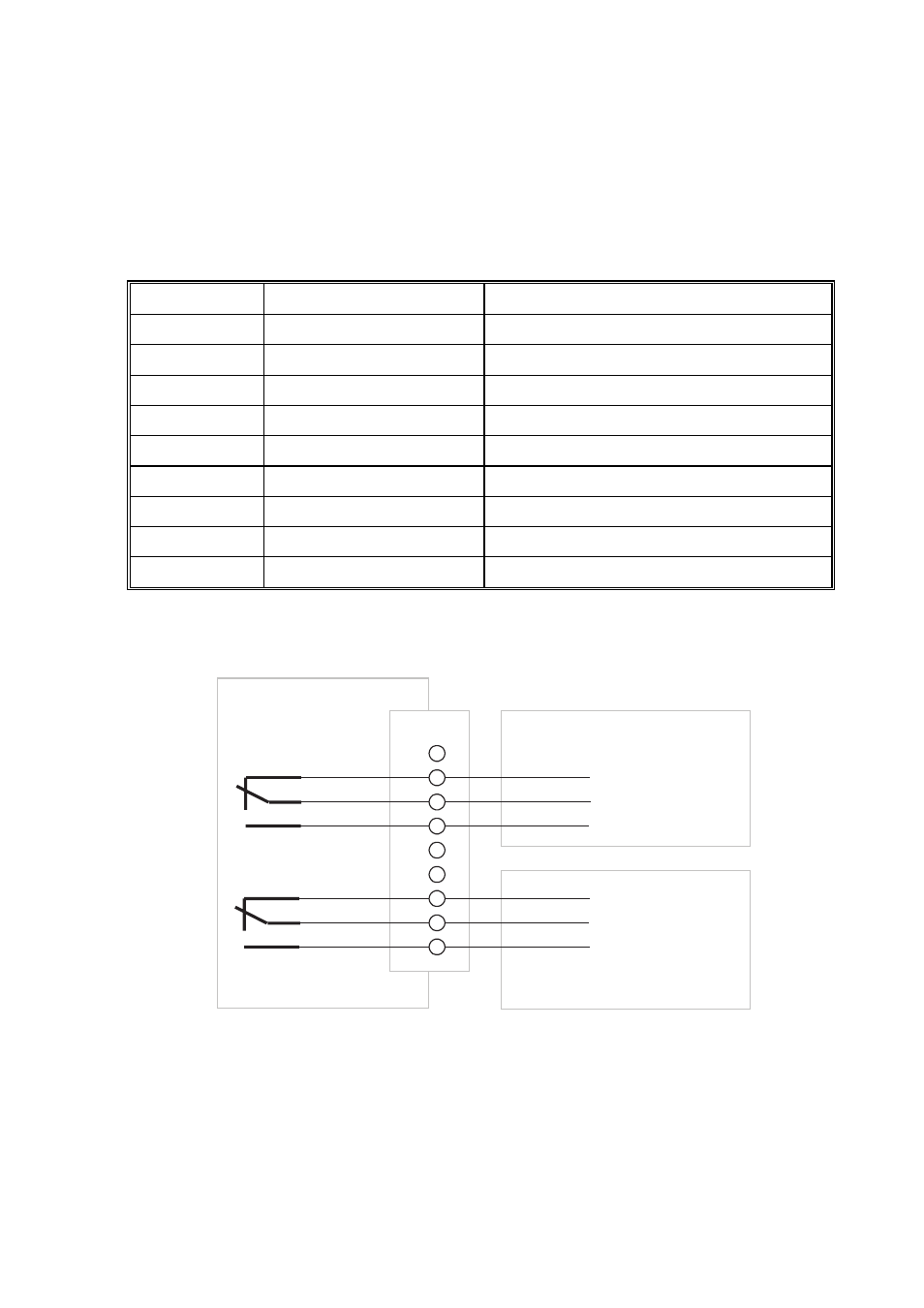
3.5 “Relay Out” Connection
Pin Assignment
Pin Specification
Description
1 -
-
2
0 – 48 V AC, 0.5 A
Switching contact, contact 2-1, switch open
3
0 – 48 V AC, 0.5 A
Switching contact, contact 2-0, switch pole
4
0 – 48 V AC, 0.5 A
Switching contact, contact 2-2, switch closed
5 -
-
6 -
-
7
0 – 48 V AC, 0.5 A
Alarm contact, contact 1-1, switch open
8
0 – 48 V AC, 0.5 A
Alarm contact, contact 1-0, switch pole
9
0 – 48 V AC, 0.5 A
Alarm contact, contact 1-2, switch closed
Table 3.5: Pin assignment of “Relay Out” connector
Diagram
PIN
1
2
3
4
5
6
7
8
9
Connection switching contact
Sunny Boy Control
Contact 2_1
Contact 2_0
Contact 2_2
Contact 1_1
Contact 1_0
Contact 1_2
Connection switching contact
Fig. 3.18: Diagram of “Relay Out” connector
The diagram shows the switches in their default switch positions (contact 1-1, contact
2-1). The default switch position of the alarm contact can be modified in the
“Setup…Interfaces…Relais Out” menu (see section 6.3).