Connection to the pv system, 1 connection to the pv system – SMA Sunny Boy Control User Manual
Page 25
Sunny Boy Control
SMA Technologie AG
User Manual
SUNBC-14:NE0206
21
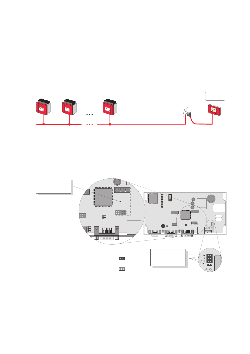
3.1 Connection to the PV System
The jumpers of the Sunny Boy Control are set at the factory to match a particular in-
terface.
Powerline Communication
Powerline
Betrieb
Operati
on
Erdsch
luss
Earth
Faul
t
Störung
Failure
Photov
oltaik-
String
wechs
elrichter
Photov
oltaic
string
inverter
SWR
1100E
Betrie
b
Ope
ration
Erdschl
uss
Earth
Fault
Störu
ng
Failure
Photov
olta
ik-Stri
ngwe
chselri
chte
r
Photo
voltaic
string
inverte
r
SWR
1100E
Betrieb
Oper
atio
n
Erdsc
hluss
Earth
Fault
Störun
g
Failure
Photov
oltaik
-Stri
ngwe
chselric
hter
Photovol
taic str
ing inv
erter
SWR
1100E
Sunny Boy
Control
PAC 1273
W
Fig. 3.3: Powerline communication
For Powerline communication with the inverters, the jumpers must be set as shown
below, and no interface module (RS232 or RS485 Piggy-Back) may be installed.
1
Jumper Settings for Powerline Communication on the COM1 Port
No
Piggy-Back
Jumper mounted:
Jumper not
mounted:
Jumper settings
for activating
onboard powerline
1
On older models of the Sunny Boy Control Plus, these jumpers cannot be reset because the circuit
board, which cannot be removed, prevents access to them.