1 analog input channels ain-1–ain-6 – SMA Sunny Boy Control User Manual
Page 103
Sunny Boy Control
SMA Technologie AG
User Manual
SUNBC-14:NE0206
99
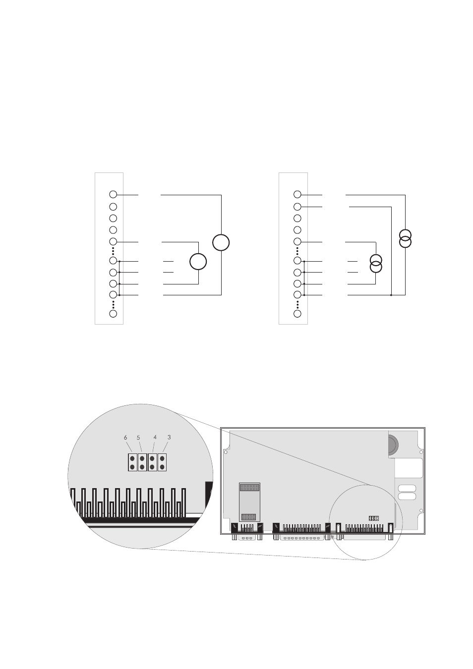
7.2.1 Analog Input Channels AIN-1–AIN-6
The analog input channels AIN-1–AIN-6 have eight variable-voltage inputs ranging
between
±
10 mV and
±
10 V at
±
20 mA.
ANAL
OG
IN
ANAL
OG
IN
ANAL
OG
IN
ANAL
OG
IN
PIN
PIN
1
1
2
2
3
3
15
15
16
16
17
17
25
25
a) Voltage measuring
b) Current measuring
AIN-1
AIN-1
AIN-1B
14
14
4
4
5
5
AGND
AGND
AGND
AGND
AGND
AGND
AGND
AGND
PIN
PIN
AIN-3
AIN-3
AIN-1
Jumper 3 mounted
=
=
Fig. 7.5: Analog input connection examples
Connecting AIN-1 and AIN-2 to AGND configures these two channels for measuring
current without having to open the device. To be able to use channels AIN-3 – AIN-6
in the same way, the device must be opened and jumpers installed inside.
Fig. 7.6: Jumper configuration for measuring current