Analog input channels ain-1–ain-6, Analog in” connector, Section 7.2 – SMA Sunny Boy Control User Manual
Page 102: 2 “analog in” connector
Sunny Boy Control
SMA Technologie AG
User Manual
SUNBC-14:NE0206
98
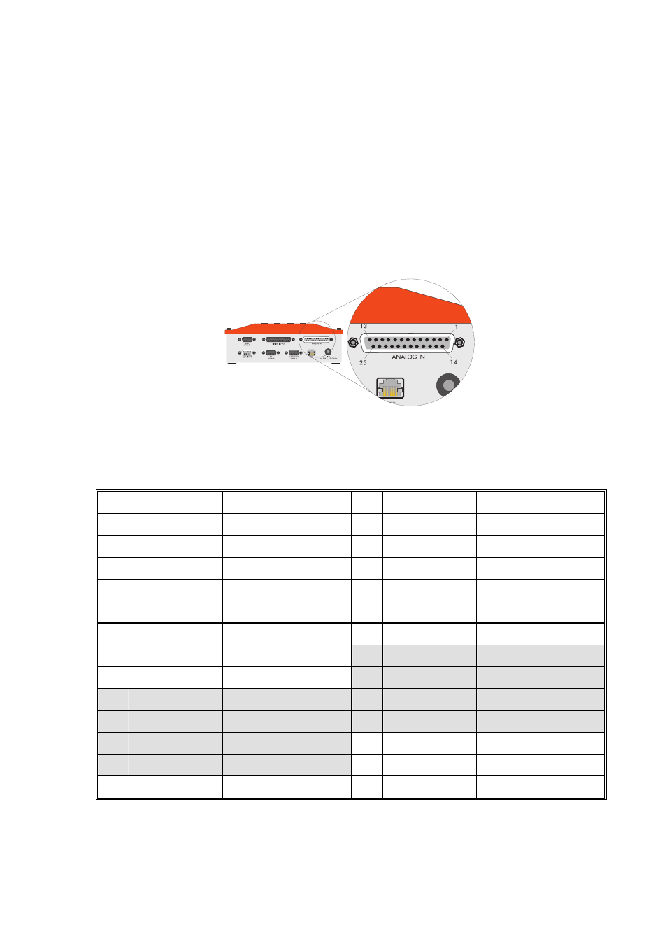
7.2 “ANALOG IN” Connector
For analog data acquisition, the Sunny Boy Control Plus offers a total of eight analog
input channels, two of which are configured for temperature sensing. The optional
SBCOP-ANA-KIT is a DB25 adapter to be connected to the “ANALOG IN” port and
providing a terminal strip that greatly simplifies the installation and connections (refer
to the quick installation guide “SBCOP-Ana-Kit-11:CD”).
Fig. 7.4: “ANALOG IN” connector
Pin Assignment
Pin
Signal Description
Pin
Signal Description
1 AIN-1
Input
14 AGND
Ground
2
AIN-1B
For measuring current
15
AGND
Ground
3 AIN-2
Input
16 AGND
Ground
4
AIN-2B
For measuring current
17
AGND
Ground
5 AIN-3
Input
18 AGND
Ground
6 AIN-4
Input
19 AGND
Ground
7 AIN-5
Input
20
AIN-7-
PT100 input V-
8 AIN-6
Input
21
AIN-8-
PT100 input V-
9
AIN-7+
PT100 input V+
22
PT100-I1-
Power source I-
10
AIN-8+
PT100 input V+
23
PT100-I2-
Power source I-
11
PT100-I1+
Power source I+
24 AGND
Ground
12
PT100-I2+
Power source I+
25 N.C.
Not
connected
13 N.C.
Not
connected
Table 7.2: Pin assignment for “ANALOG IN” connector