SMA Sunny Boy Control User Manual
Page 36
Sunny Boy Control
SMA Technologie AG
User Manual
SUNBC-14:NE0206
32
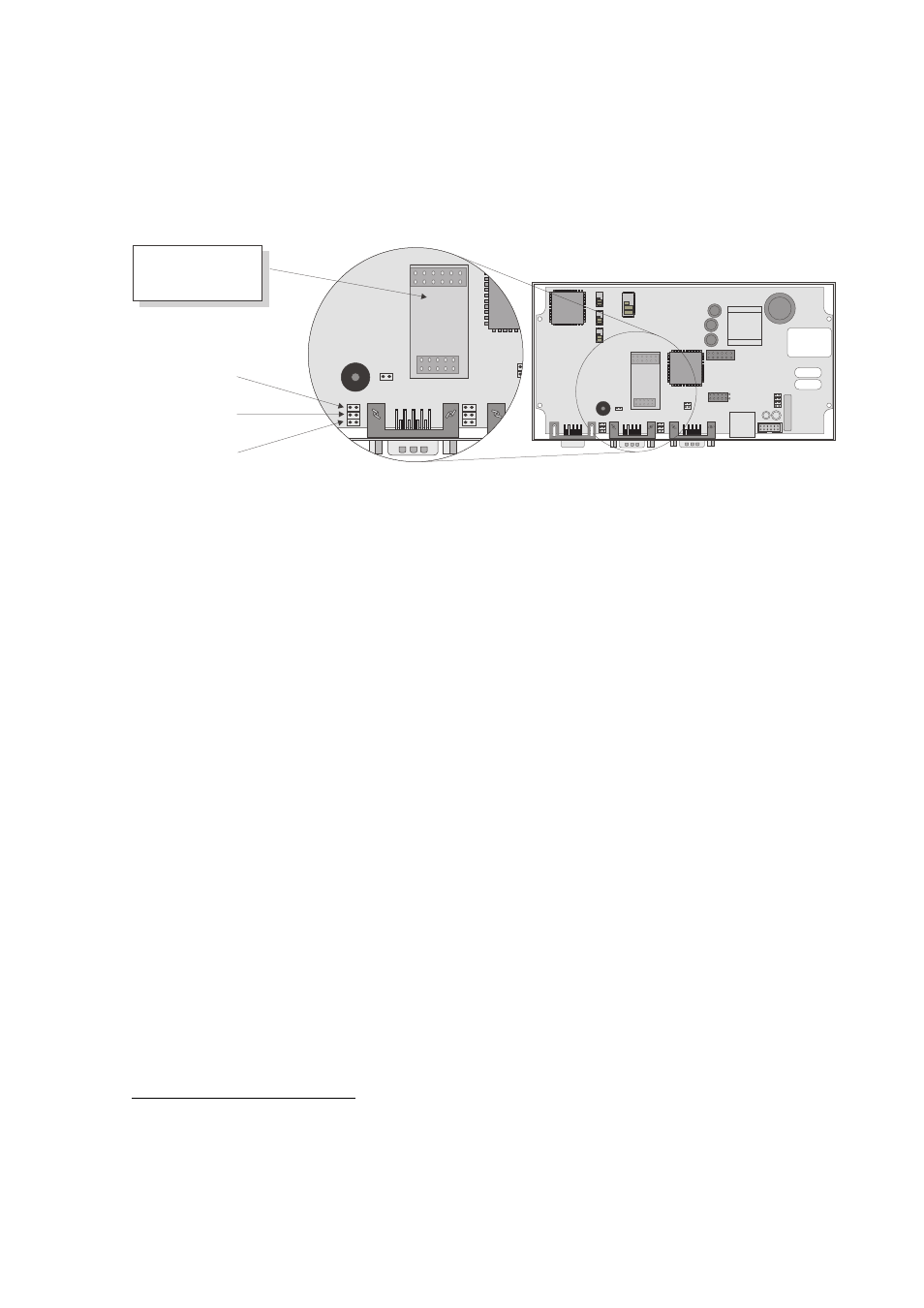
Jumper settings for an RS485 connection to the “PC (COM2)” interface
of the Sunny Boy Control
1
A
B
C
Insert RS485
Piggy-Back here
Jumper A:
Termination of the RS485 cable. The data cable must
be terminated on both ends by either setting jumper A
or bridging pins 7 and 9 of the connector. The required
resistance is 120
Ω
. The default setting is “not termi-
nated”.
Jumpers B and C:
Pull-up/pull-down resistances for the RS485 signal. The
RS485 pull-up/pull-down resistances are achieved by
either setting jumpers B and C on the Sunny Boy Con-
trol or using a cable plug with integrated resistors. The
required resistances are 680
Ω
. The default setting is
“pull-up/pull-down activated”. Only one device on the
RS485 bus needs to provide the pull-up/pull-down resis-
tances.
1
On older models of the Sunny Boy Control Plus, these jumpers cannot be modified because the up-
per circuit board, which cannot be removed, prevents access to them.