24 v power supply, 1 24 v power supply, Sc:realt. data – SMA Sunny Boy Control User Manual
Page 110: Diag ext+24v, Ok š, Diag dout/din

Sunny Boy Control
SMA Technologie AG
User Manual
SUNBC-14:NE0206
106
Diagnostic Channels
The menu “Realtime Data” of the Sunny Boy Control Plus gives access to the di-
agnostic channels of the digital interface.
[SC:REALT. DATA]
:::
‡+Diag Ext+24V…
Diagnosis of external voltage supply
…OK Š
OK,
Error
+Diag DOUT/DIN…
Diagnosis of digital output & input channels
…OK
OK,
Error
:::
Fig. 7.13: Diagnosis of digital interface
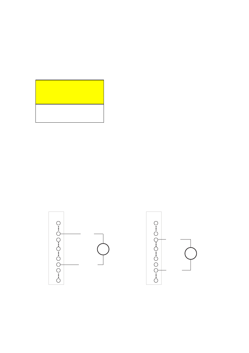
7.3.1 24 V Power Supply
The 24 V DC power required to operate the digital channels must be supplied exter-
nally. If only a few channels are used, it may be most cost-effective to connect a small
standard 15 V AC transformer to the 15VAC pins and let the Sunny Boy Control Plus
convert this internally by means of a bridge rectifier. If however more channels are
used, a 24 V DC power source must be connected to the +24VDC, +24VDC,
DGND, and DGND pins.
PIN
=
a) DC voltage supply
b) AC voltage supply
DGND
+24 V DC
15 … 22 V
~
15 V AC
15 V AC
18 … 27 V
25
21
20
18
9
8
7
1
DIGIT
AL
IN/OUT
PIN
25
21
20
18
9
8
7
1
DIGIT
AL
IN/OUT
Fig. 7.14: Supplying power to the digital interface (example)
With an external 24 V DC power source, the diagnostic channel “+Diag Ext+24V”
can be used to check whether the necessary voltage is being supplied.
