SMA Sunny Boy Control User Manual
Page 33
Sunny Boy Control
SMA Technologie AG
User Manual
SUNBC-14:NE0206
29
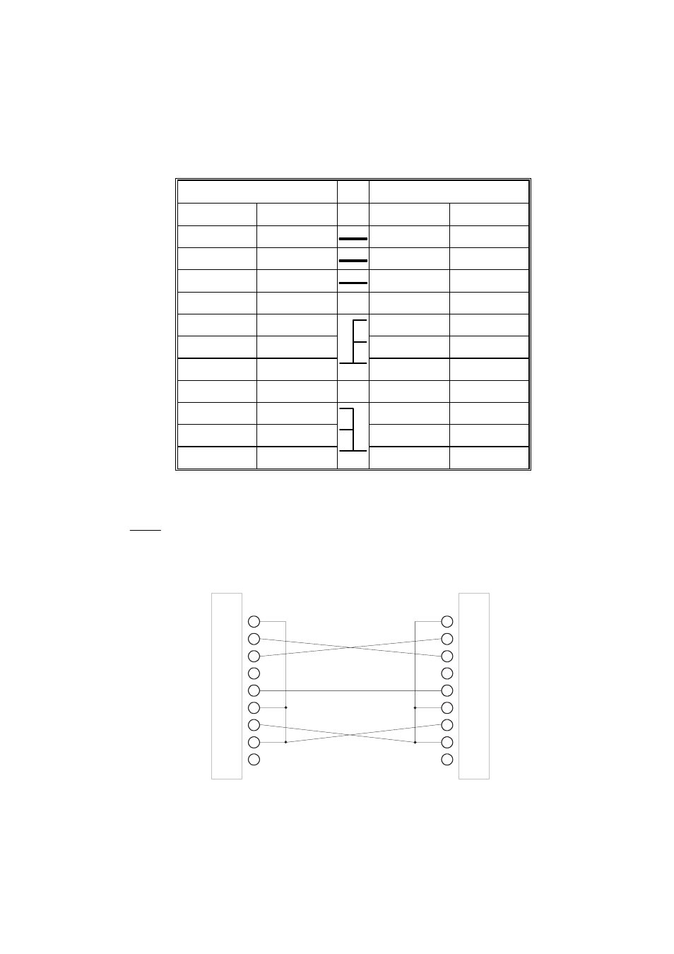
Pin assignment of a DB9-DB9 cable for a PC-to-Sunny Boy Control
connection
DB9 plug
DB9 plug
Signal Pin Pin Signal
/RXD 2
3 /TXD
/TXD 3
2 /RXD
GND 5
5 GND
1
DCD
6
DSR
RTS 7
8 CTS
DCD 1
DSR 6
CTS 8
7 RTS
Table 3.3: Pin assignment of a DB9-DB9 cable for PC connection
: These pins are connected together.
Pins 1, 6, and 8 on both ends are bridged.
PIN
1
2
3
4
5
6
7
8
9
PIN
1
2
3
4
5
6
7
8
9
DB9 socket
DB9 socket
Fig. 3.11: Diagram of DB9-DB9 cable for PC connection
This manual is related to the following products:
See also other documents in the category SMA Equipment:
- SUNNY PORTAL (75 pages)
- SB 2.5-1VL-40 (60 pages)
- SB 2.5-1VL-40 Service Manual (36 pages)
- SB 240 (78 pages)
- FLX Pro 17 (12 pages)
- FLX Series GSM Option Kit (48 pages)
- FLX Series Sensor Interface Option (51 pages)
- FLX Series PLA Option (62 pages)
- FLX Series (248 pages)
- 25000TL (52 pages)
- 25000TL Installation (40 pages)
- 25000TL Service Manual (46 pages)
- CBL-DC-CMB8-10 (24 pages)
- 25000TL Quick Installation Guide (36 pages)
- STP 60-10 Replacing a Defective Fan (12 pages)
- STP 60-10 Replacing Defective Surge Arresters (12 pages)
- Webconnect Systems in SUNNY PORTAL (69 pages)
- STP 12000TL (68 pages)
- STP 60-US-10 Installation (232 pages)
- 485 Data Module Type B (24 pages)
- STP 12000TL Quick Installation Guide (28 pages)
- 1000-US (52 pages)
- STP 24000TL-US (78 pages)
- STP 17000TL (60 pages)
- STP 20000TL (2 pages)
- SB 6000TL Service Manual (46 pages)
- MULTIFUNCTION RELAY (32 pages)
- SB 5000TL (60 pages)
- SB 5000TL Quick Installation Guide (32 pages)
- FANKIT01-10 (24 pages)
- SB 7700TL-US (28 pages)
- FANKIT02-10 (24 pages)
- SB 7700TL-US Installation (96 pages)
- SUNNY MINI CENTRAL (48 pages)
- DC Disconnect Switch For SB 3800-U (32 pages)
- SB 4000-US (100 pages)
- DB-DC-DISCON (4 pages)
- SB 3800-U (86 pages)
- POWER BALANCER (28 pages)
- SB 8000-US (104 pages)
- SB 11000TL‑US (40 pages)
- SMC 11000TL (24 pages)
- SBCBTL6 (36 pages)
- SB 11000TL‑US Installation (92 pages)
- SMC 11000TL Installation (96 pages)