SMA Sunny Boy Control User Manual
Page 26
Sunny Boy Control
SMA Technologie AG
User Manual
SUNBC-14:NE0206
22
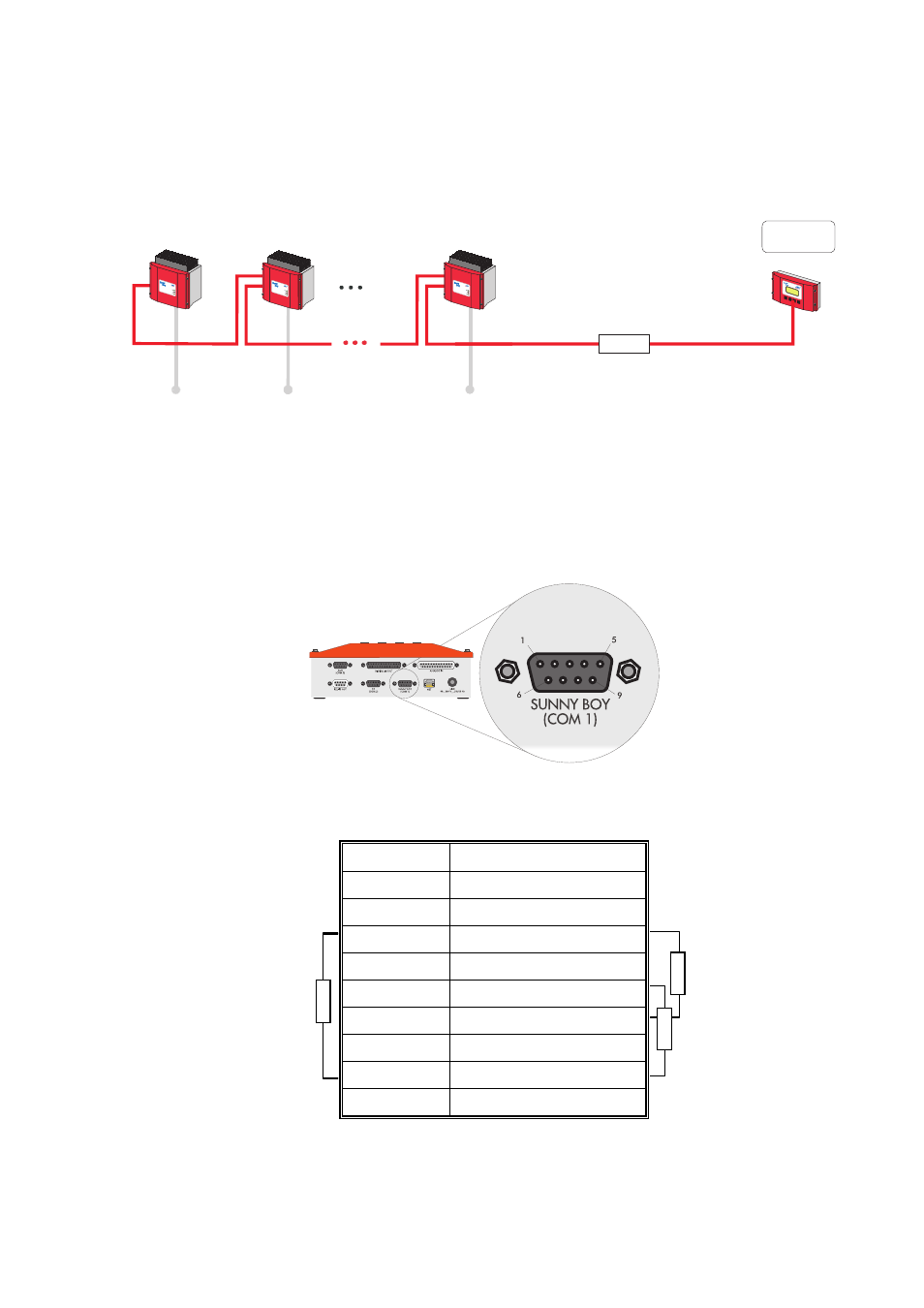
RS485 Connection Between Sunny Boys and Sunny Boy Control
Sunny Boy
Control
PAC 1273
W
Betrieb
Oper
ation
Erdschluss
Earth
Fault
Störun
g
Failure
Photovoltaik
-Strin
gwec
hselrichter
Photovo
ltaic
string
inverter
SWR
1100E
Betrieb
Operatio
n
Erdsch
luss
Earth
Fault
Störung
Failur
e
Photovoltaik
-Stri
ngw
echselrichter
Photovolt
aic stri
ng invert
er
SWR
1100E
Betrieb
Operati
on
Erdschluss
Earth
Fault
Störung
Failur
e
Photovoltaik
-Stringwechselrich
ter
Phot
ovolt
aic stri
ng invert
er
SWR
1100E
RS485
Fig. 3.4: Sunny Boys connected via RS485
Pin Assignment
The signals shown in the table below are available only when the optional RS485
Piggy-Back has been installed. The standard Sunny Boy Control does not support the
“SUNNY BOY (COM1)” interface. Instead, it uses Powerline communication to
communicate with the Sunny Boy inverters.
Fig. 3.5: “SUNNY BOY (COM1)” connector
Pin
RS485 signal
1 PE
2 Data
+
3 Data
+
4
-
680
Ω
120
Ω
termination 5
GND
6 +5V
7
Termination -> Data +
680
Ω
8 Data
-
Pull-up /
pull-down
resistors
9 Data
-
Table 3.1: Pin assignment of “SUNNY BOY (COM1)” interface
on RS485 Piggy-Back