Gasboy Fuel Point PLUS Vehicle User Manual
Page 50
Fuel Point PLUS Vehicle Installation and Configuration Manual
50
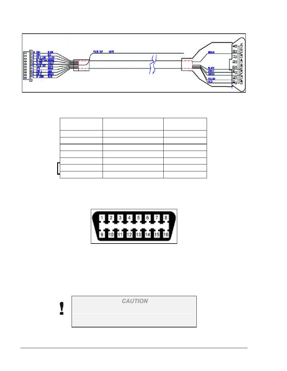
Harness Wire
OBD-2 Pin
Description
White*
To white wire in VIU
Pulse out to VIU
Yellow**
7
K-line
Green***
6
CAN H
Gray***
14
CAN L
Red****
16
VIN+
Black
4
VIN-
Blue****
16
+POLE
Figure 3-10.OBDII Connector Wiring to DataPass Harness
Table 3-8. Harness OBDII Connections
Short
*
Do not connect if VIU in exists
**
If K-line communication is utilized, do not connect Green & Gray wires
***
If CANBUS communication is utilized, do not connect Yellow wire
**** Short is connected between red and blue wires if engine hour output is not used
Figure 3-11. OBDII Connector Pins Layout
Proceed as follows:
1. Locate the standard On Board Diagnostics (OBD II, see Figure 3-7) connector (usually
hidden behind one of the panels below the steering wheel, or near the pedals)
2. Remove the Diagnostics connector panel (see Figure 3-12)
CAUTION
Confirm the bus protocol in use before proceeding
with the installation. Consult vehicle's technical
specifications if needed.