Gasboy Fuel Point PLUS Vehicle User Manual
Page 33
Fuel Point PLUS Vehicle Installation and Configuration Manual
33
Figure 2-17. Tightening the Clamps
4. Lock and tighten it and then cut the edges using the CV Joint Banding Tool and cutter
5. Using a drilling machine or pliers, insert the provided conduit termination nipples at
each side of the flexible conduit
6. Thread the coil wire through the flexible conduit
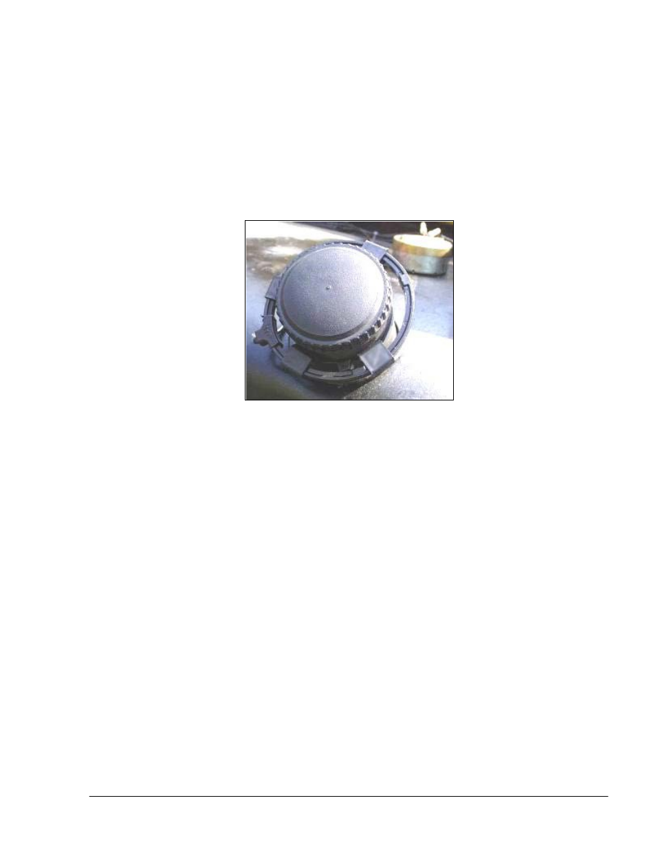
7. Verify that the cover can be properly closed upon completion of the installation.
Then close the fuel inlet cover. (see Figure 2-18)
Figure 2-18. Complete Coil Installation on Long Neck Inlet
2-6.4.2. Short Neck Fuel Inlet Installation
This installation is implemented in fuel tanks where the fuel tank inlet does not protrude sufficiently
from the fuel tank surface. This installation method makes use of horizontal positioning of the
molded coil clamps.
Proceed as follows:
1. Use a Fuel Ring of optimal size which can be easily placed around the fuel tank inlet and
allows the opening and closing of the fuel tank inlet cover (use a coil larger than the fuel
tank inlet diameter by approximately 35 mm)
2. Insert a metal wire into the molded clamps in the designated slots. Use adequate number
of clamps to position the coil firmly around the fuel tank inlet (use three to five clamps
per coil size). Make sure to position the clamps horizontally as shown in Figure 2-19