Gasboy Fuel Point PLUS Vehicle User Manual
Page 23
Fuel Point PLUS Vehicle Installation and Configuration Manual
23
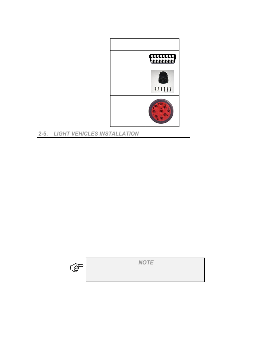
Table 2-7. Common Bus Connectors
Type
Connector
OBD II
6-PIN round
connector
9-PIN round
connector
2-5.
LIGHT VEHICLES INSTALLATION
2-5.1.
General
Two techniques, or a combination of both, are available for installing the coil unit:
By gluing the coil's bottom surface to the vehicle
By gluing the coil's bottom surface to the vehicle and clamping it
Place the coil unit around the fuel inlet. Pay special attention to the coil's flat part direction –
verify that the bottom legs surface of the plastic molded coil type faces the surface of the
vehicle. In general, it is possible to place the coil in a number of ways; still, it is advisable to
place the coil in the center of the fuel tank inlet to achieve better performance.
The ID chip is installed by gluing it to the vehicle and by securing the unit using a special screw
in order to prevent removal and theft. The chip's installation is performed either in a concealed
place in the luggage compartment, or in a visible place near the fuel tank inlet. When properly
secured against theft, the unit becomes damaged the moment it is pulled away from the vehicle
after installation is completed. It is required to place the ID chip in a less accessible location for
theft and tampering. A distance of up to 100cm between the coil and the ID chip is permitted.
2-5.2.
Preliminary Instructions
NOTE
Warranty does not cover defects or damage caused
by improper installation.
In order to prevent possible problems and difficulties during the installation, please verify that:
1. The coil in use is larger than the fuel tank inlet to improve coil assembly
2. The coil is being kept away from metal surfaces, maintaining an air gap of at least 5mm
3. The coil is assembled as close as possible to the Wireless Nozzle Reader coil when the
fueling nozzle is inserted