Figure 4-42. 101 control switch state diagram -39 – Basler Electric BE1-851 User Manual
Page 95
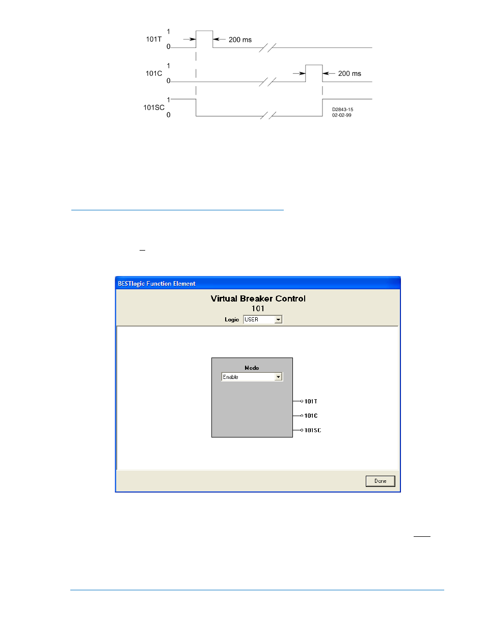
Figure 4-42. 101 Control Switch State Diagram
When the virtual control switch is controlled to trip, the 101T output pulses TRUE (closed) for
approximately 200 milliseconds and the 101SC output goes FALSE (open). When the virtual control
switch is controlled to close, the 101SC output pulses TRUE (closed). The status of the slip contact output
is saved to nonvolatile memory so that the relay will power up with the contact in the same state as when
the relay was powered down.
BESTlogic™ Settings for Virtual Breaker Control Switch
BESTlogic settings are made from the BESTlogic Function Element screen in BESTCOMS. Figure 4-43
illustrates the BESTCOMS screen used to select BESTlogic settings for the Virtual Breaker Control 101
element. To open the BESTlogic Function Element screen for Virtual Breaker Control 101, select Virtual
Switches from the Screens pull-down menu. Then select the BESTlogic button in for the 101 element.
Alternately, setting may be made using the SL-101 ASCII command.
Figure 4-43. BESTlogic Function Element Screen, 101
At the top center of the BESTlogic Function Element screen is a pull-down menu labeled Logic. This
menu allows viewing of the BESTlogic settings for each preprogrammed logic scheme. User must be
selected on this menu in order to allow changes to the mode and inputs of the element.
Enable the Virtual Breaker Control 101 element by selecting its mode of operation from the Mode pull-
down menu. Select Done when the settings have been completely edited.
Table 4-19 summarizes the BESTlogic settings for Virtual Breaker Control Switch.
9289900990 Rev R
BE1-851 Protection and Control
4-39