Virtual switches, 43 - virtual selector switches, Bestlogic™ settings for virtual selector switches – Basler Electric BE1-851 User Manual
Page 92: Virtual switches -36, 43 - virtual selector switches -36
Virtual Switches
43 - Virtual Selector Switches
BE1-851 relays have four virtual selector switches that can provide manual control, locally and remotely,
without using physical switches and/or interposing relays. Only two virtual selector switches are provided
when style option 1 is V or W. Each virtual switch can be set for one of three modes of operation to
emulate virtually any type of binary (two position) switch. An example would be an application that
requires a recloser or 51N ground cutoff. The traditional approach might be to install a switch on the panel
and wire the output to a contact sensing input on the relay. Instead, a virtual switch can be used to reduce
costs with the added benefit of being able to operate the switch both locally through the HMI and remotely
from a substation computer or through a modem connection to a remote operator’s console.
The state of the switches can be controlled from the HMI or ASCII command interface. The BESTlogic
mode setting can set control actions. When set for the On/Off/Pulse mode, each switch can be controlled
to open (logic 0), close (logic 1), or pulse such that the output toggles from its current state to the opposite
state and then returns. Additional modes allow the switch operation to be restricted. In the On/Off mode,
the switch emulates a two-position selector switch, and only open and close commands are accepted. In
the Off/Momentary On mode, a momentary close, spring return switch is emulated and only the pulse
command is accepted. Because switch status information is saved in nonvolatile memory, the relay
powers up with the switches in the same state as when the relay was powered down.
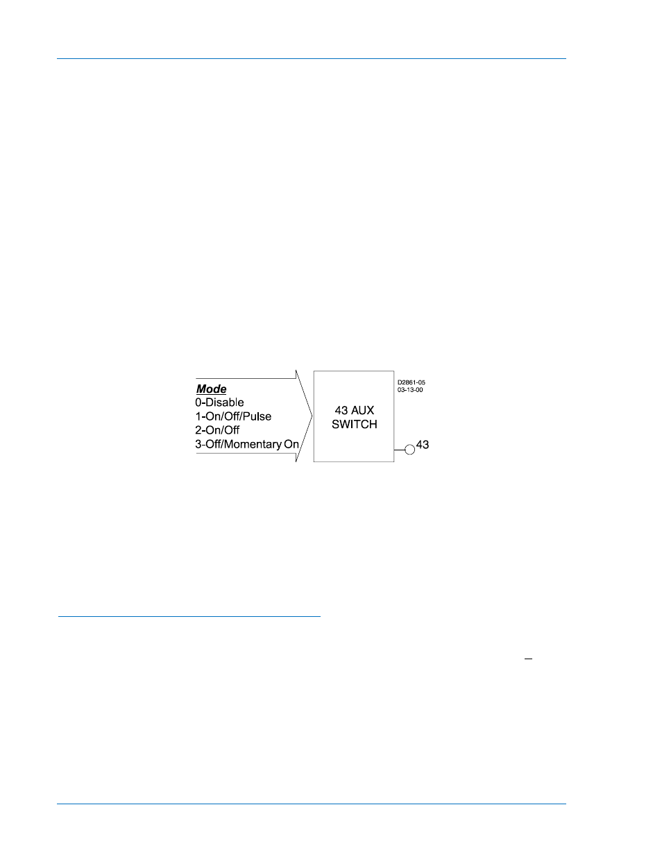
Each virtual selector switch function block (see Figure 4-39) has one output: 43, 143, 243, or 343. The
output is TRUE when the switch is in the closed state; the output is FALSE when the switch is in the open
state. Since both the output and the inverse of the output of these switches can be used as many times
as desired in your programmable logic, they can emulate a switch with as many normally open and
normally closed decks as desired.
Figure 4-39. Virtual Selector Switches Logic Block
User specified labels could be assigned to each virtual switch and to both states of each switch. In the
previous differential cutoff switch example, you might enable one of the switches in BESTlogic as On/Off
and connect the output of that switch to the Block input of the 51P protection element block. This would
disable the differential when the switch is closed (logic 1) and enable it when the switch is open (logic 0).
For the application, you might set the switch label to be 51_CUTOFF (10 character maximum). The
closed position on the switch might be labeled DISABLD (7 character maximum) and the open position
might be labeled NORMAL. Section 7, BESTlogic Programmable Logic, has more details about setting
user programmable names for programmable logic variables.
BESTlogic™ Settings for Virtual Selector Switches
BESTlogic settings are made from the BESTlogic Function Element screen in BESTCOMS. Figure 4-40
illustrates the BESTCOMS screen used to select BESTlogic setting for the Virtual Switch element. To
open the BESTlogic Function Element screen for Virtual Switch, select Virtual Switches from the Screens
pull-down menu. Then select the BESTlogic button for the 43, 143, 243, or 343 element. Alternately,
settings may be made using SL-
4-36
BE1-851 Protection and Control
9289900990 Rev R