Pickup and dropout testing, 50t pickups and dropouts, Pickup and dropout testing -3 – Basler Electric BE1-851 User Manual
Page 291: 50t pickups and dropouts -3, Table 13-2. contact sensing turn-on voltage -3, Table 13-3. output commands -3
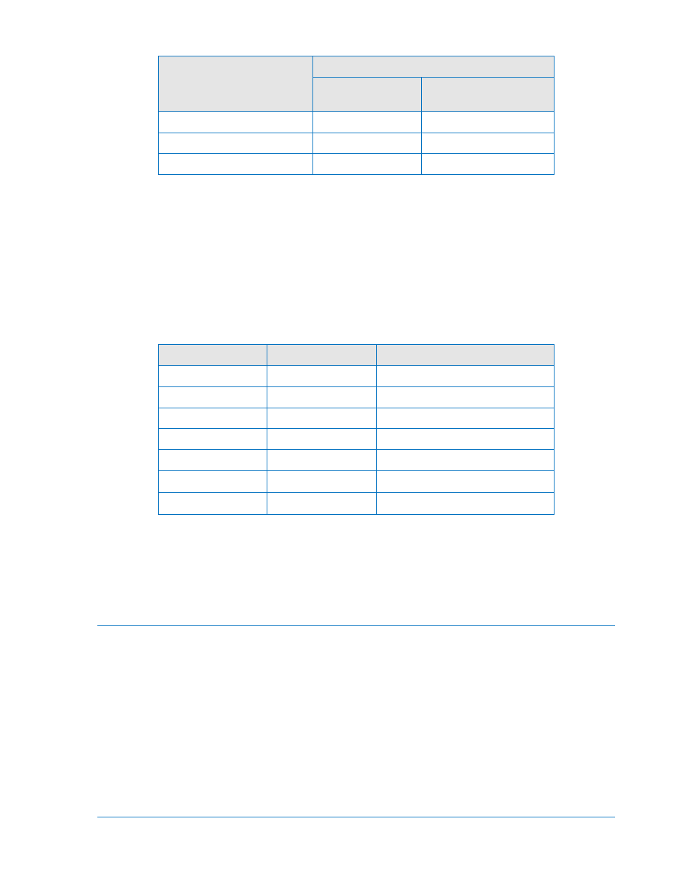
Table 13-2. Contact Sensing Turn-On Voltage
Nominal Control Voltage
Contact Sensing Turn-On Voltage
Jumper Installed
(Low Position)
Jumper Not Installed
(High Position)
24 Vdc
N/A
Approx. 5 Vdc
48/125 Vac/dc
26 to 38 Vac/dc
69 to 100 Vac/dc
125/250 Vac/dc
69 to 100 Vac/dc
138 to 200 Vac/dc
Step 2:
Transmit the command “RG-STAT”. Examine response line “INPUT(1-4) STATUS:” to verify
that all inputs were detected.
Step 3:
Transmit the commands “ACCESS=851”, “CS-OUT=ENA”, “CO-OUT=ENA”, and “EXIT;Y” to
enable the output control override capability of the relay.
Step 4:
Using Table 13-3 as a guide, transmit the commands listed and verify that the appropriate
output contacts change state. When each command is transmitted, the corresponding output
will be pulsed briefly. An ohmmeter or continuity tester may be used to monitor the output
contact status.
Table 13-3. Output Commands
Output
Terminals
Commands
OUT1 (N.O.)
C1 & C2
CS-OUT1=P;CO-OUT1=P
OUT2 (N.O.)
C3 & C4
CS-OUT2=P;CO-OUT2=P
OUT3 (N.O.)
C5 & C6
CS-OUT3=P;CO-OUT3=P
OUT4 (N.O.)
C7 & C8
CS-OUT4=P;CO-OUT4=P
OUT5 (N.O.)
C9 & C10
CS-OUT5=P;CO-OUT5=P
ALARM (N.C.) ∗
C11 & C12
CS-OUTA=P;CO-OUTA=P
ALARM (N.O.) ∗
C11 & C12
CS-OUTA=P;CO-OUTA=P
∗
The style number determines if the ALARM output is N.C. or N.O. See Section 1, General Information,
Model and Style Number Description.
Step 5:
Disable the control override ability if desired by transmitting the commands “ACCESS=851”,
“CS-OUT=DIS”, “CO-OUT=DIS”, and “EXIT;Y” to the relay.
Pickup and Dropout Testing
Transmit the frequency command, “SG-FREQ=50” or “SG-FREQ=60”, depending on which frequency the
relay is to be tested at. Transmit the commands “ACCESS=851”, CS-GROUP=0”, and “CO-GROUP=0” to
select settings group 0. Save the settings by transmitting the command “EXIT;Y”.
50T Pickups and Dropouts
Step 1:
Transmit the following scheme to the relay:
ACCESS=851
SL-N=NONE
YES
SL-N=PU50
SL-50T=1,0
SL-VO1=50TPT+50TNT
EXIT;Y
9289900990 Rev R
BE1-851 Testing and Maintenance
13-3