Rs-485 connector, Irig input and connections, Rs-485 connector -22 – Basler Electric BE1-851 User Manual
Page 284: Irig input and connections -22, Figure 12-24. rs-485 db-37 to be1-851 -22, Table 12-3. rs-485 pin-outs (com2) -22
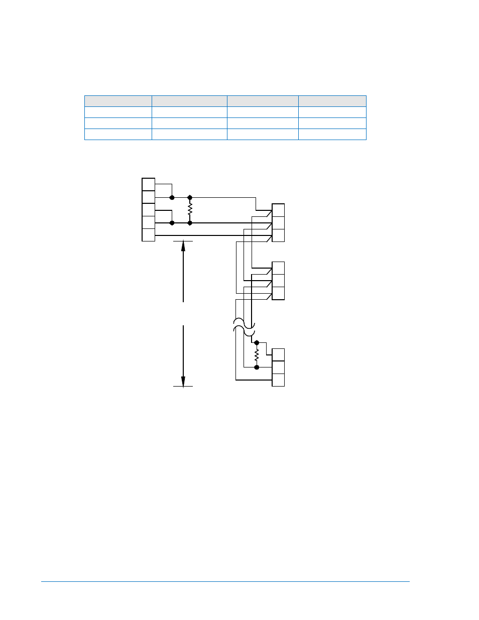
RS-485 Connector
The RS-485 connector is a three-position terminal block connector designed to interface to a standard
communication cable. A twisted-pair cable is recommended. Connector pin numbers, functions, names,
and signal directions are shown in Table 12-3. A cable connection diagram is provided in Figure 12-24.
Table 12-3. RS-485 Pin-outs (COM2)
Terminal
Function
Name
Direction
A
Send/Receive A
(SDA/RDA)
In/Out
B
Send/Receive B
(SDB/RDB)
In/Out
C
Signal Ground
(GND)
N/A
Figure 12-24. RS-485 DB-37 to BE1-851
IRIG Input and Connections
The IRIG input is fully isolated and supports IRIG Standard 200-98, Format B002. The demodulated (dc
level-shifted) input signal must be 3.5 volts or higher to be recognized as a high logic level. The maximum
acceptable input voltage range is +10 to –10 volts. Input burden is nonlinear and rated at approximately
4kΩ at 3.5Vdc and approximately 3kΩ at 20Vdc.
IRIG connections are located on a terminal block shared with the RS-485 and input power terminals.
Terminal designations and functions are shown in Table 12-4.
02-20-97
D2557-11
22
6
4
A
B
C
3 POSITION TB
DB-37 FEMALE
TO BE1-851
TO RS422/RS485
19
24
C
B
A
A
B
C
4000'
MAX
.
COM 2
BE1-851
BE1-851
COM 2
BE1-851
COM 2
R
t
t
R
R = OPTIONAL TERMINATING
t
RESISTOR (120 OHMS TYP.)
A3
A4
A5
A3
A4
A5
A3
A4
A5
12-22
BE1-851 Installation
9289900990 Rev R