Figure 4-11. overcurrent screen, 50t tab -12 – Basler Electric BE1-851 User Manual
Page 68
5.x.1.6 where x equals 1 for Setting Group 0, 2 for Setting Group 1, 3 for Setting Group 2, and 4 for
Setting Group 3.
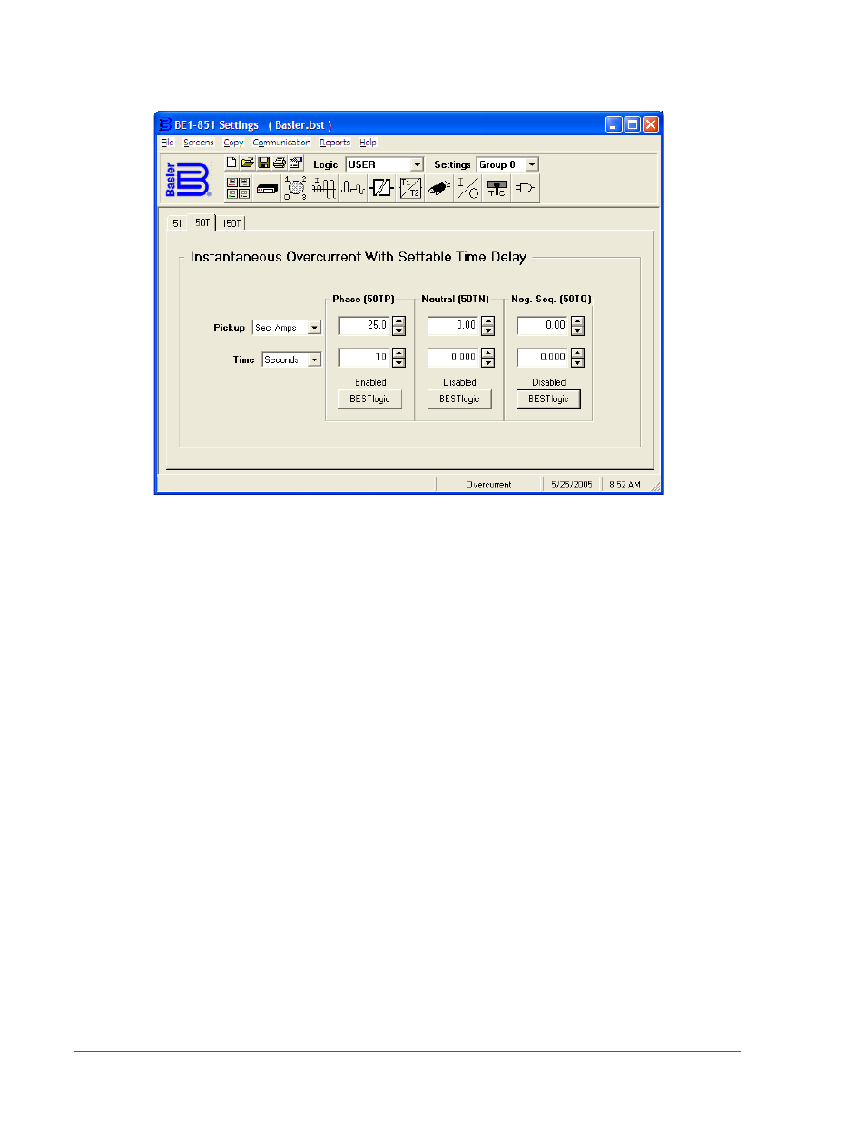
Figure 4-11. Overcurrent Screen, 50T Tab
At the top center of the screen is a pull-down menu labeled Logic. This menu allows viewing of the
BESTlogic settings for each preprogrammed logic scheme. User or custom logic must be selected on this
menu in order to allow changes to be made to the mode and inputs of the element. See Section 7,
BESTlogic Programmable Logic, Logic Schemes.
To the right of the Logic pull-down menu is a pull-down menu labeled Settings. The Settings menu is used
to select the setting group that the entered settings will apply to.
Operating settings for the 50T and 150T functions consist of Pickup and time delay (Time) values. The
Pickup value determines the level of current required for the function block to start timing toward a trip.
Time delays (Time) can be set in milliseconds, seconds, or cycles. The default is milliseconds if no unit of
measure is specified. Minimum timing resolution is to the nearest quarter-cycle. A time delay setting of
zero makes the element instantaneous with no intentional time delay.
The default unit of measure for the Pickup setting is secondary amps. Primary amps (Pri Amps), per unit
amps (Per U Amps), and percent amps (% Amps) can also be selected as the pickup setting unit of
measure. The unit of measure for the Time setting that represents the element’s time delay defaults to
milliseconds. It is also selectable for seconds, minutes, and cycles.
If time delay settings are made in cycles, they are converted to seconds or milliseconds (per the nominal
frequency setting stored in EEPROM) before being stored and rounded to the nearest whole millisecond.
See Section 3, Input and Output Functions, Current Measurement Functions, for more information about
this setting. If the nominal frequency setting is being changed from the default (60 hertz) and time delay
settings are being set in cycles, the frequency setting should be entered and saved before making any
time delay settings changes.
For setting up the negative-sequence overcurrent protection, see Negative-Sequence Overcurrent
Protection later in this section.
Using the pull-down menus and buttons, make the application appropriate settings to the instantaneous
overcurrent element. Table 4-5 summarizes the operating settings for Instantaneous Overcurrent
Protection.
4-12
BE1-851 Protection and Control
9289900990 Rev R