Creating or customizing a logic scheme, Sending and retrieving relay settings, Retrieving relay settings – Basler Electric BE1-851 User Manual
Page 150: Sending relay settings, Debugging the logic scheme, User input and output logic variable names, Creating or customizing a logic scheme -10, Sending and retrieving relay settings -10, Debugging the logic scheme -10, User input and output logic variable names -10
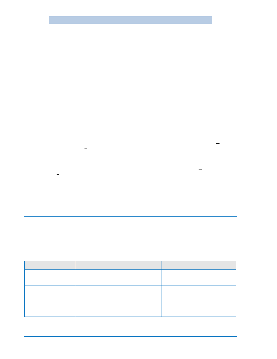
CAUTION
Always remove the relay from service before changing or modifying the active
logic scheme. Attempting a logic scheme change while the relay is in service
could generate unexpected or unwanted outputs.
Creating or Customizing a Logic Scheme
Before customizing a preprogrammed logic scheme, the scheme must be renamed. The following
procedure outlines the process of customizing or creating a logic scheme:
Step 1. Copy the preprogrammed logic scheme.
Step 2. Rename the scheme with a unique, non-preprogrammed name.
Step 3. Using BESTCOMS, enable or disable the desired relay functions.
Step 4. Edit the logic expressions as required.
Step 5. Save the changes. Refer to Section 14, BESTCOMS Software, for more information on how to
save and export settings files.
Sending and Retrieving Relay Settings
Retrieving Relay Settings
To retrieve settings from the relay, the relay must be connected to a computer through a serial port. Once
the necessary connections are made, settings can be downloaded from the relay by selecting Download
Settings from Device on the Communication pull-down menu.
Sending Relay Settings
To send settings to the relay, the relay must be connected to a computer through a serial port. Once the
necessary connections are made, settings can be uploaded to the relay by selecting Upload Settings to
Device on the Communication pull-down menu.
Debugging the Logic Scheme
If there are problems with a customized logic scheme, the RG-STAT command can be used to check the
status of all logic variables. More information about the RG-STAT command can be found in Section 6,
Reporting and Alarms.
User Input and Output Logic Variable Names
Assigning meaningful names to the inputs and outputs makes sequential events reports easier to analyze.
Input and output logic variable names are assigned by typing them into the appropriate text box on the
related BESTCOMS screen. All of the BE1-851’s inputs, outputs, and 43 switches have labels that can be
edited. Tables 7-3, 7-4, and 7-5 show the range and purpose of each label. Alternately, labels may be
edited using the SN-[name]=[label] ASCII command.
Table 7-3. Label Settings for INPUTS
Setting
Range/Purpose
Default
Name
1 to 10 characters.
User label to replace default label.
INPUT_x
(where x = 1, 2, 3, or 4)
Energized State
1 to 7 characters.
User label to replace default label.
TRUE
De-Energized State
1 to 7 characters.
User label to replace default label.
FALSE
7-10
BE1-851 BESTlogic™ Programmable Logic
9289900990 Rev R