Delta/wye transformer application, Delta/wye transformer application -19, Table 4-10. fault type multiplier -19 – Basler Electric BE1-851 User Manual
Page 75
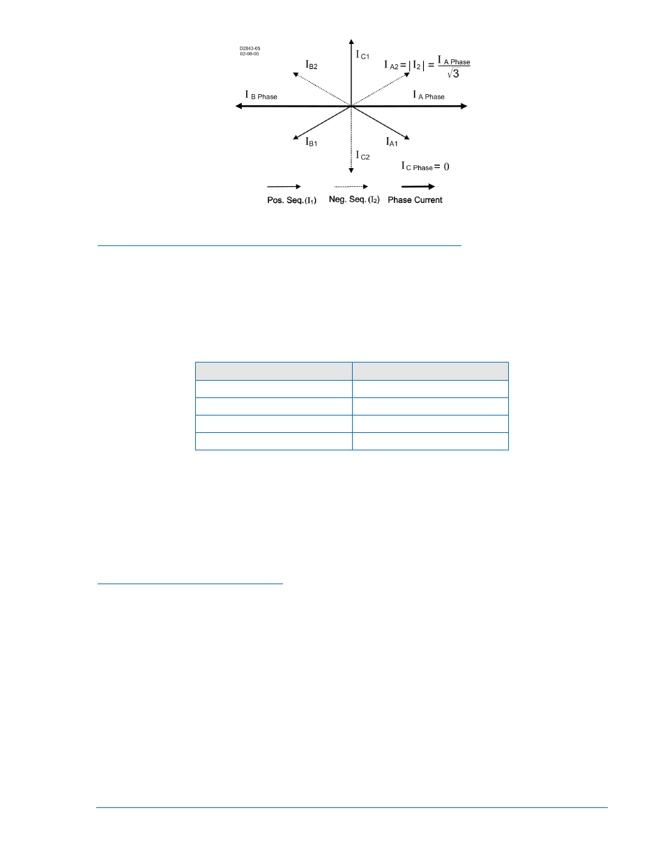
Figure 4-17. Sequence Components for an A-B Fault
Coordination Settings for Negative-Sequence Overcurrent Protection
The 51Q settings should be checked for coordination with phase-only sensing devices such as
downstream fuses and reclosers and/or ground relays. To plot the negative-sequence time current
characteristics on the same plot for the phase devices, you need to multiply the negative-sequence
element pickup value by the correct multiplier. The multiplier is the ratio of phase current to negative-
sequence current for the fault type for which you are interested. To plot the negative-sequence time
current characteristics on the same plot for the ground devices, you need to multiply the pickup value by
the multiplier for phase-to-ground faults. See Table 4-10.
Table 4-10. Fault Type Multiplier
Fault Type
Multiplier
Ph-Ph
m =1.732
Ph-Ph-G
m > 1.732
Ph-G
m =3
3-phase
m = infinity
For example, a downstream phase 51 element has a pickup of 150 amperes. The upstream 51Q element
has a pickup of 200 amperes. To check the coordination between these two elements for a phase-to-
phase fault, the phase overcurrent element would be plotted normally with pickup at 150 amperes. The
51Q element would be shifted to the right by the appropriate factor m. Thus, the characteristic would be
plotted on the coordination graph with pickup at: (200 amperes) * 1.732 = 346 amperes.
Generally, for coordination with downstream phase overcurrent devices, phase-to-phase faults are the
most critical to consider. All other fault types result in an equal or greater shift of the time current
characteristic curve to the right on the plot.
Delta/Wye Transformer Application
Often, the phase relays on the delta side of a delta/wye transformer must provide backup protection for
faults on the wye side. For faults not involving ground, this is not a problem since the phase relays will
see 1.0 per unit fault current for three-phase faults and 2/√3 (1.15) per unit fault current for phase-to-
phase faults. However, for faults involving ground, the sensitivity is reduced because the zero-sequence
components are trapped in the delta and not seen by the delta-side phase relays. The phase relays will
see only 1/√3 (0.577) per unit current for phase-to-ground faults.
Negative-sequence overcurrent protection is immune to the effect caused by the zero-sequence trap and
30° phase shift provided by the delta/wye transformer. For a phase-to-ground fault, the magnitude of the
negative-sequence components is 1/3 the magnitude of the total fault current. On a per unit basis, this is
true for the fault current on the delta side of the transformer as well. (The previous statement specifies per
unit since the actual magnitudes will be adjusted by the inverse of the voltage ratio of the delta/wye
transformer.) Thus, backup protection for phase-to-ground faults on the wye side of the transformer can
be obtained by using negative-sequence overcurrent protection on the delta side with the pickup
sensitivity set at 1/3 per unit of the magnitude of the phase-to-ground fault for which you wish to have
backup protection.
9289900990 Rev R
BE1-851 Protection and Control
4-19