Basler Electric BE1-851 User Manual
Page 93
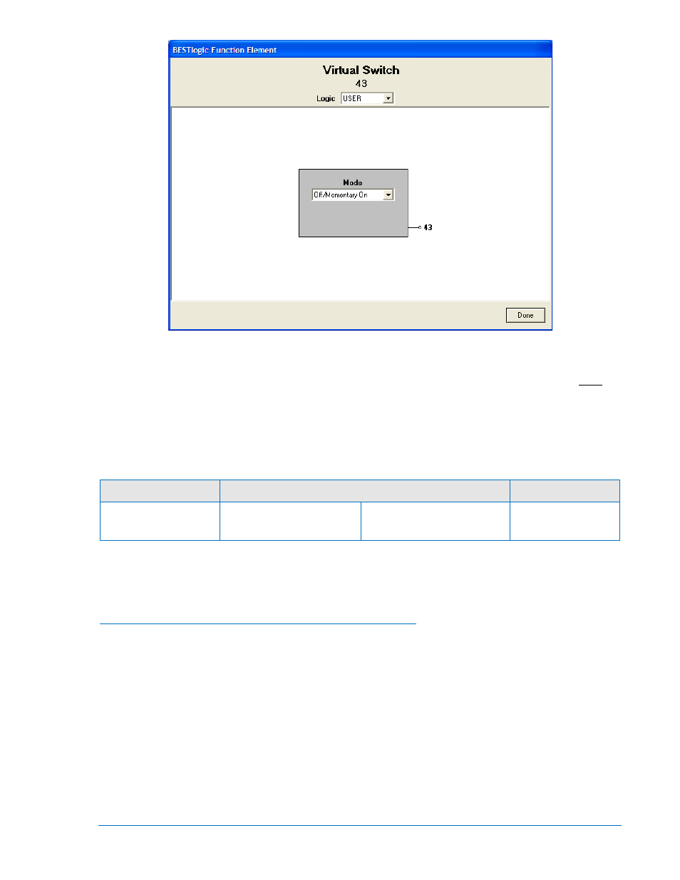
Figure 4-40. BESTlogic Function Element Screen, 43
At the top center of the BESTlogic Function Element screen is a pull-down menu labeled Logic. This
menu allows viewing of the BESTlogic settings for each preprogrammed logic scheme. User must be
selected on this menu in order to allow changes to the mode and inputs of the element.
Enable the Virtual Switch element by selecting its mode of operation from the Mode pull-down menu.
Select Done when the settings have been completely edited.
Table 4-18 summarizes the BESTlogic settings for Virtual Selector Switches.
Table 4-18. BESTlogic Settings for Virtual Selector Switches
Function
Range/Purpose
Default
Mode
0 = Disabled
1 = On/Off/Pulse
2 = On/Off
3 = Off/Momentary On
0
Example 1. Make the following settings to the 43 Virtual Switch element. See Figure 4-40.
Logic:
User
Mode:
Off/Momentary On
Select Before Operate Control of Virtual Selector Switches
The state of each virtual selector switch can be controlled at the human-machine interface (HMI) through
Screens 2.1.1 through 2.1.4. Control is also possible through the ASCII command interface by using the
select-before-operate command’s CS-x43 (control select-virtual switch) and CO-x43 (operate select-
virtual switch). This is not possible through BESTCOMS. A state change takes place immediately without
having to execute an EXIT – SAVE settings command.
The virtual switch control commands require the use of select-before-operate logic. First, the command
must be selected using the CS-x43 command. After the select command is entered, there is a 30 second
window during which the CO-x43 control command will be accepted. The control selected and the
operation selected must match exactly or the operate command will be blocked. If the operate command
is blocked an error message is output.
9289900990 Rev R
BE1-851 Protection and Control
4-37