Operating settings for breaker failure protection, Figure 4-20. breaker failure screen -22 – Basler Electric BE1-851 User Manual
Page 78
Example 1.
Make the following BESTlogic settings to the Breaker Failure element. See Figure 4-19.
Mode:
Enable
Initiate:
VO1
Block:
IN4
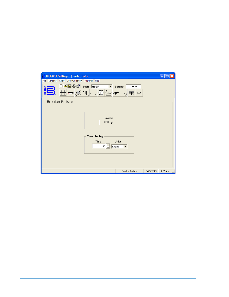
Operating Settings for Breaker Failure Protection
Operating settings are made using BESTCOMS. Figure 4-20 illustrates the BESTCOMS screen used to
select operational settings for the Breaker Failure element. To open the Breaker Failure screen, select
Breaker Failure from the Screens pull-down menu. Alternately, settings may be made using the SP-BF
ASCII command or from the HMI interface using Screen 5.5.1.1.
Figure 4-20. Breaker Failure Screen
At the top center of the screen is a pull-down menu labeled Logic. This menu allows viewing of the
BESTlogic settings for each preprogrammed logic scheme. User or custom logic must be selected on this
menu in order to allow changes to be made to the mode and inputs of the element. See Section 7,
BESTlogic Programmable Logic, Logic Schemes.
To the right of the Logic pull-down menu is a text box labeled Settings. The word “Global” appears in the
text box, indicating the element is not assigned to any setting group. The operating settings for the
Breaker Failure element consist of a single time delay (Time). The time delay can be set in milliseconds,
seconds, or cycles. The default is milliseconds if no unit of measure is specified. The minimum timing
resolution is to the nearest quarter-cycle. A time delay setting of zero makes the element instantaneous
with no intentional time delay.
If the time delay settings are made in cycles, they are converted to seconds or milliseconds before being
stored. This conversion is based on the nominal frequency setting stored in EEPROM. See Section 3,
Input and Output Functions, Current Measurement Functions, for more information on this setting. If the
user is changing the nominal frequency setting from the default (60 Hz) and setting the time delays in
cycles, the frequency setting should be entered and saved to EEPROM first by entering E;Y.
Using the pull-down menus and buttons, make the application appropriate settings to the Breaker Failure
element.
Table 4-12 summarizes the operating settings for Breaker Failure Protection.
4-22
BE1-851 Protection and Control
9289900990 Rev R