Dovetailing procedure, Dovetailing procedure -13, Figure 12-14. f1 case, cutout dimensions -13 – Basler Electric BE1-851 User Manual
Page 275: N figure 12-14
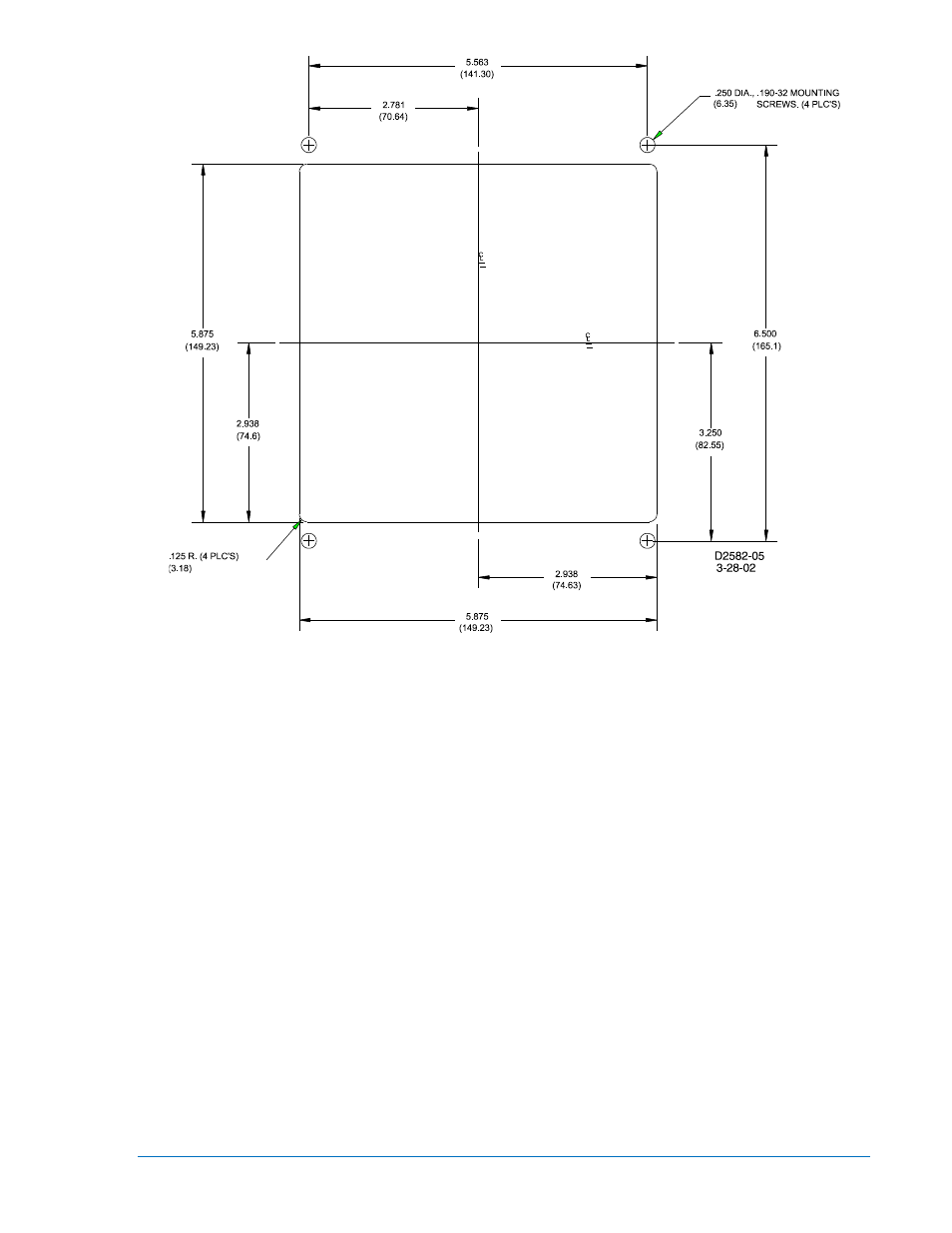
Figure 12-14. F1 Case, Cutout Dimensions
Dovetailing Procedure
Basler H1 cases can be interlocked by means of a tenon and mortise on the left and right sides of each
case. The following paragraphs describe the procedure of dovetailing two cases. Figure 12-15 illustrates
the process.
Step 1: Remove the draw-out assembly from each case by rotating the two captive, front panel screws
counterclockwise and then sliding the assembly out of the case. Observe electrostatic
discharge (ESD) precautions when handling the draw-out assemblies.
Step 2: Remove the mounting bracket from the side of each case where the two cases will mate. Each
bracket is held in place by four Phillips screws.
Step 3: The rear panel must be removed from one of the cases in order for the two cases to be joined.
On that panel, remove the Phillips screw from each corner of the rear panel except for the
screw at the upper left-hand corner (when looking at the rear of the case). This screw is closest
to Terminal Strip A.
Step 4: Turn the screw nearest to Terminal Strip A counterclockwise until the rear panel can be
removed from the case. If you have difficulty removing this screw, use the alternate method
described in Step 4a. Otherwise, proceed to Step 5.
Step 4a: Use a Torx
T15 driver to remove the two screws attaching Terminal Strip A to the rear panel.
Remove the terminal strip and set it aside. Remove the remaining Phillips screw from the rear
panel and set the rear panel aside.
Step 5: Arrange the two cases so that the rear dovetailed edge of the case without a rear panel is
aligned with the front dovetailed edge of the case with the rear panel installed. Once the
dovetails are aligned, slide the cases together.
9289900990 Rev R
BE1-851 Installation
12-13