Fault reporting, Logic expressions for fault reporting, Trip – Basler Electric BE1-851 User Manual
Page 121: Fault reporting -19, Logic expressions for fault reporting -19, Figure 6-11. tcm with other devices -19
CAUTION
Applications that place other device inputs in parallel with the breaker trip coil
may not perform as desired. The connection of other devices in parallel with
the trip coil causes a voltage divider to occur when the breaker or trip circuit is
open. This may cause false tripping of the other devices and prevent the BE1-
851 trip circuit monitor from reliably detecting an open circuit. Contact Basler
Electric for advice on this application.
The circuit monitor sensing element has the same rating as the power supply
voltage. If the trip circuit voltage is significantly greater than the power supply
voltage (for example, when using a capacitor trip device), the user should
program the BE1-851 to use one of the other output relays for tripping. In this
situation, the trip circuit monitor function will not be available
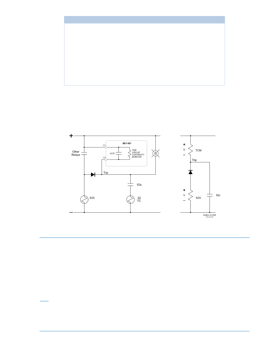
Figure 6-11, a 62x auxiliary relay is shown. In this case, the impedance of the 62x coil is small compared
to the impedance of the TCM circuit so the TCM is always at logic 1. This prevents the TCM logic from
working even if the trip coil is open. Normally, when redundant systems are used, each relay system is on
an individual circuit and the sensing input for each relay system is isolated from the tripping circuit. The
impedance of the TCM sensing circuit is the same as the contact sensing inputs. See Section 1, General
Information, General Specifications, Control Inputs, for this information.
Figure 6-11. TCM with Other Devices
Fault Reporting
The fault reporting function records and reports information about faults that have been detected by the
relay. The BE1-851 provides many fault reporting features. These features include Targets, Fault
Summary Reports, Oscillographic Records, and Sequence of Events Recorder Reports.
Logic Expressions for Fault Reporting
Logic expressions are used to define the three conditions for fault reporting. These conditions are TRIP,
PICKUP, and LOGIC trigger. Figure 6-8 and Table 6-8 illustrate how each of these logic expressions is
used by the various relay functions. Note that even though BESTlogic expressions are used to define
these conditions, these expressions are not included here. Section 7, BESTlogic Programmable Logic,
provides information about using BESTlogic to program the relay.
Trip
Trip expressions are used by the fault reporting function to start logging targets for an event and to record
fault current magnitudes at the time of trip. The trip expression is used to illuminate the Trip LED on the
HMI. The Trip LED will turn on and remain on as long as the trip expression is true. The Trip LED will
remain on (or “sealed-in”) after the trip expression becomes false if targets are associated with the trip.
The breaker monitoring function uses the trip expression to start counting the breaker operate time.
9289900990 Rev R
BE1-851 Reporting and Alarms
6-19