Outputs, Hardware outputs and virtual outputs, Retrieving output status – Basler Electric BE1-851 User Manual
Page 49: Outputs -7, Hardware outputs and virtual outputs -7, Retrieving output status -7
Outputs
BE1-851 relays have five general-purpose output contacts (OUT1 through OUT5) and one fail-safe,
normally open/normally closed, alarm output contact (OUTA). Each output is isolated and rated for
tripping duty. OUT1 through OUT5 are “Form A” (normally open) and OUTA is “Form A or B” (normally
open or closed depending on BE1-851 style number, case option).
Hardware Outputs and Virtual Outputs
Output contacts OUT1 through OUT5 and OUTA are driven by BESTlogic™ expressions for VO1 through
VO5 (Virtual Outputs 1 through 5) and VOA (Virtual Output A). The use of each output contact is
completely programmable so you can assign meaningful labels to each output and to the logic 0 and logic
1 states of each output. Section 7, BESTlogic Programmable Logic, has more information about
programming output expressions in your programmable logic schemes.
A virtual output (VOn) exists only as a logical state inside the relay. A hardware output is a physical output
relay contact. BESTlogic expressions for VO1 through VO5 (Virtual Outputs 1 through 5) and VOA
(Virtual Output A) drive output contacts OUT1 through OUT5 and OUTA. The state of the output contacts
can vary from the state of the output logic expressions for three reasons:
•
The relay trouble alarm disables all hardware outputs.
•
The programmable hold timer is active.
•
The select-before-operate function overrides a virtual output.
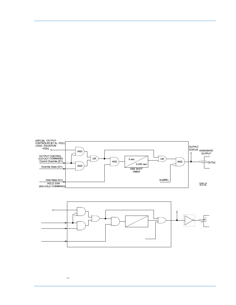
Figure 3-6 shows a diagram of the output contact logic for the general-purpose output contacts. Figure
3-7 illustrates the output contact logic for the fail-safe alarm output contact.
Figure 3-6. Output Logic, General Purpose Output Contacts
Figure 3-7. Output Logic, Fail-Safe Alarm Output Contact
Retrieving Output Status
The relay’s outputs can be monitored from the Metering screen. To open the Metering screen select
Metering from the Reports pull-down menu. To begin viewing the relay’s metered values, select the Start
Polling button in the bottom right hand corner of the screen.
0.200
Sec
0
Sec
OR
ONE SHOT
TIMER
AND
OUT[A]
HARDWARE
OUTPUT
OUTPUT
STATUS
AND
AND
OR
Control Override (0/1)
Override State (0/1)
Hold State (0/1)
VO[A]
VIRTUAL OUTPUT
CONTROLLED BY SL-VO[n]
LOGIC EQUATION
HOLD ENA
(SG-HOLD COMMAND)
OUTPUT CONTROL
(CO-OUT COMMAND)
ALMREL
D2647-19
03-13-06
NOT
9289900990 Rev R
BE1-851 Input and Output Functions
3-7