Retrieving breaker duty information, Breaker clearing time monitoring, Breaker alarms – Basler Electric BE1-851 User Manual
Page 116: Breaker alarms -14
Retrieving Breaker Duty Information
Breaker duty values can be read at HMI Screen 4.3.2. Duty values can be changed by using the front
panel Edit key. Write access to reports is required to edit breaker duty values. Duty values can also be
read or changed through the communication ports using the RB-DUTY command.
Breaker Clearing Time Monitoring
The breaker clearing time monitor tracks the time from when a
Recording” feature (SG-TRIGGER=
detector is FALSE (current = 0 amps in all three phases). The trip output (i.e., 51PT, 51NT, etc.) of any
protective element can be programmed to the Fault Recording
the trip output of the protective element goes TRUE, the
is reported as a line in the fault summary reports. See the Fault Reporting subsection for more information
about the TRIP logic expression and Fault Summary Reports.
Breaker clearing time can be monitored to give an alarm when the value exceeds a threshold. The
following Breaker Alarms subsection provides more information about this feature.
Breaker Alarms
Three alarm points are included in the programmable alarms for checking breaker-monitoring functions.
Each alarm point can be programmed to monitor any of the three breaker monitoring functions: operations
counter, interruption duty, or clearing time. An alarm threshold can be programmed to monitor each
function. Alternately, three different thresholds can be programmed to monitor one of the monitored
functions.
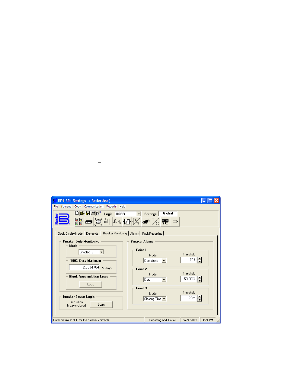
Breaker Alarms settings are made using BESTCOMS. Figure 6-7 illustrates the BESTCOMS screen used
to select settings for the Breaker Alarms function. To open the Reporting and Alarms screen, select
Reporting and Alarms from the Screens pull-down menu. Then select the Breaker Monitoring tab.
Settings may also be made using the SB-BKR ASCII command.
At the top left of the screen is a pull-down menu labeled Logic. This menu allows viewing of the
BESTlogic settings for each preprogrammed logic scheme. User must be selected on this menu in order
to allow changes to be made to the mode and inputs of the function.
Figure 6-7. Reporting and Alarms Screen, Breaker Monitoring Tab
6-14
BE1-851 Reporting and Alarms
9289900990 Rev R