Reclosing, Reclosing -28, Figure 4-30. reclosing logic block -28 – Basler Electric BE1-851 User Manual
Page 84
At the top center of the screen is a pull-down menu labeled Logic. This menu allows viewing of the
BESTlogic settings for each preprogrammed logic scheme. User or custom logic must be selected on this
menu in order to allow changes to be made to the mode and inputs of the element.
To the right of the Logic pull-down menu is a pull-down menu labeled Settings. The Settings menu is used
to select the setting group that the element’s settings apply to. See Section 7, BESTlogic Programmable
Logic, Logic Schemes.
Using the pull-down menus and buttons, make the application appropriate settings to the Logic Timers
element. Table 4-14 summarizes the operating settings for General Purpose Logic Timers.
Table 4-14. Operating Settings for General Purpose Logic Timers
Setting
Range
Increment
Unit of Measure
Default
T1 Time,
T2 Time
0 to 999 ms
1
Milliseconds
0
0.1 to 9999 sec.
0.1 for 0.1 to 9.9 sec.
Seconds
1.0 for 10 to 9999 sec.
0 to 599,940 (60 Hz)
0 to 499,950 (50Hz)
∗
Cycles
∗
Time delays less than 10 cycles can be entered to the nearest 0.1 cycles through the HMI. All time
delays can be entered to the nearest 0.01 cycles from the ASCII command interface. Time delays entered
in cycles are converted to milliseconds or seconds. Increment precision after conversion is limited to that
appropriate for each of those units of measure.
Example 1.
Make the following operating settings to the 62 element. See Figure 4-29.
Logic:
User
Setting:
Group 0
Time Units:
ms
T1 Time:
100
T2 Time:
0
Retrieving General Purpose Logic Timers Status from the Relay
The status of each logic variable can be determined from the ASCII command interface by using the RG-
STAT (report general-status) command. Status cannot be determined using BESTCOMS. See Section 6,
Reporting and Alarms, General Status Reporting, for more information.
Reclosing
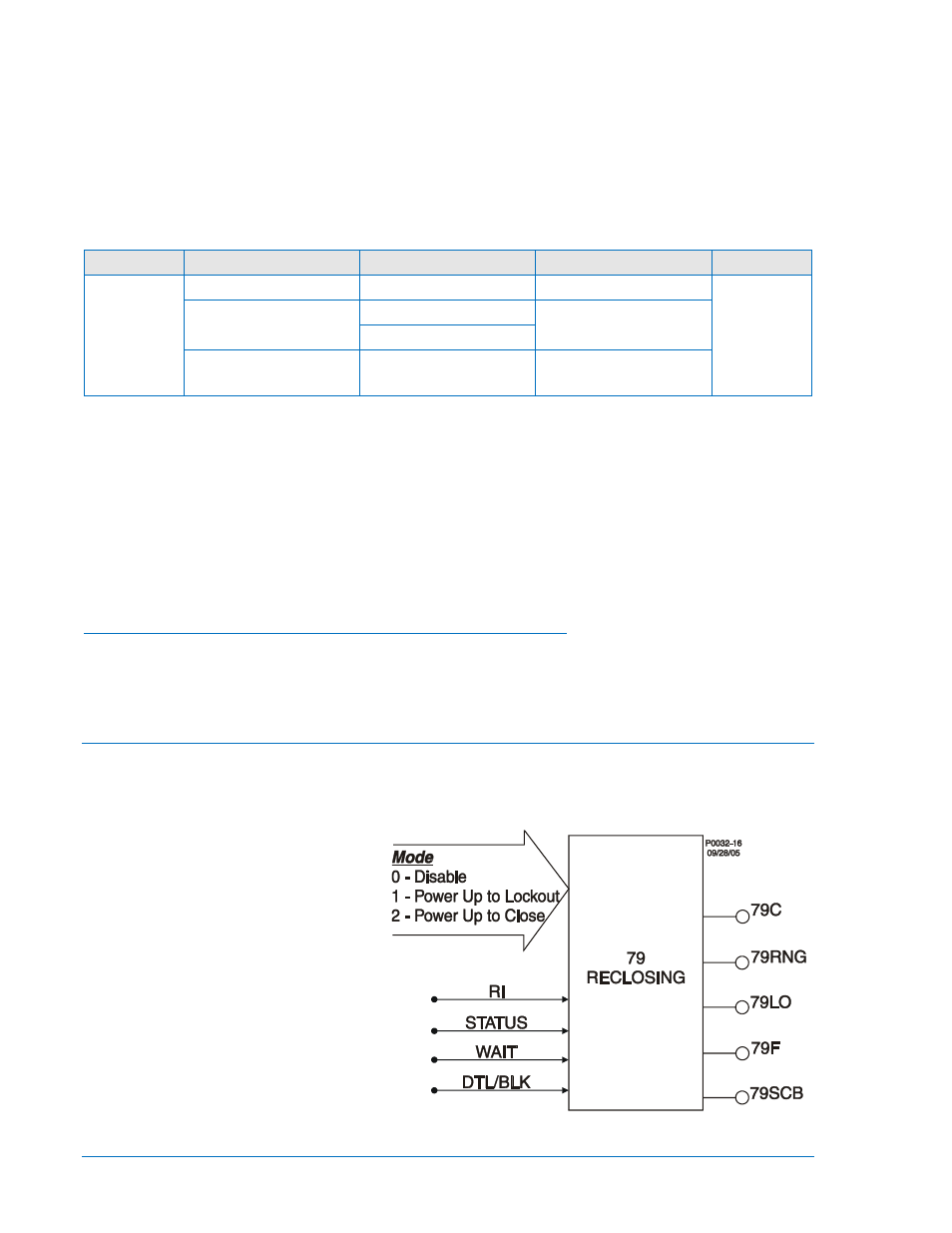
The BE1-851 reclosing function provides up to four reclosing attempts that can be initiated by a protective
trip or by one of the contact sensing inputs. The reclosers allow supervisory control and coordination of
tripping and reclosing with other system devices. Any of the four recloser shots can be used to select a
different setting group when the appropriate shot is reached in a reclosing sequence. This change in
setting groups allows changing protection
coordination during the reclosing
sequence. For example, you could have a
fast 51 curve on the first two trips in the
reclosing sequence and then switch to a
new group on the second reclose that
uses a slow 51 curve. Detailed
information about relay setting groups can
be found earlier in this section under the
heading of Setting Groups. Recloser
function block inputs and outputs are
shown in Figure 4-30 and are described in
the following paragraphs. An overall logic
diagram for the recloser function is shown
in Figure 4-38.
Figure 4-30. Reclosing Logic Block
4-28
BE1-851 Protection and Control
9289900990 Rev R