Basler Electric BE1-851 User Manual
Page 70
characteristic, the user can append an R to the selected time current characteristic curve. A
programmable curve is available that can be used to create a custom curve by selecting coefficients in
the inverse time characteristic equation.
When the measured current is above the pickup threshold, the pickup logic output, 51PPU (for example)
= TRUE and inverse timing is started per the selected characteristic. If the current stays above pickup
until the function times out, the trip logic output, 51PT (for example) = TRUE. If the current falls below the
dropout ratio, which is 95% of pickup, the function will either reset instantaneously or begin timing to reset
depending on the user’s setting.
The phase overcurrent protective functions include three independent comparators and timers, one for
each phase. If the current increases above the pickup setting for any one phase, the pickup output
asserts. If the trip condition is TRUE for any phase, the trip logic output asserts.
If the target is enabled for the function block, the target reporting function will record a target for all
phases that are above pickup when the protective function trip output is TRUE and the fault recording
function trip logic expression is TRUE. See Section 6, Reporting and Alarms, Fault Reporting, for more
details on the target reporting function.
BESTlogic™ Settings for Time Overcurrent Protection
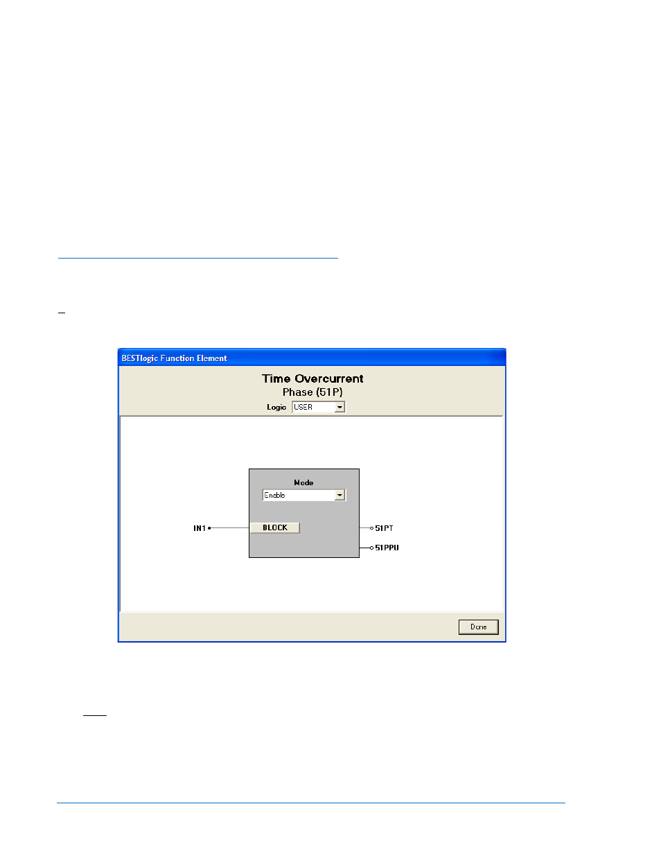
BESTlogic settings are made from the BESTlogic Function Element screen in BESTCOMS. Figure 4-13
illustrates the BESTCOMS screen used to select BESTlogic settings for the Time Overcurrent element.
To open the BESTlogic Function Element screen for Time Overcurrent, select Overcurrent from the
Screens pull-down menu and select the 51 tab. Then select the BESTlogic button for the element you
wish to edit. Alternately, settings may be made using the SL-x51 ASCII command.
Figure 4-13. BESTlogic Function Element Screen, Phase (51P)
At the top center of the BESTlogic Function Element screen is a pull-down menu labeled Logic. This
menu allows viewing of the BESTlogic settings for each preprogrammed logic scheme. User or custom
logic must be selected on this menu in order to allow changes to the mode and inputs of the element.
Enable the time overcurrent function by selecting its mode of operation from the Mode pull-down menu.
When enabled, this element is connected to the CT input circuits.
To connect the blocking control, select the Block button on the BESTlogic Function Element screen. The
BESTlogic Expression Builder screen will open. Select the expression type to be used. Then, select the
BESTlogic variable or series of variables to be connected to the input. Select Save when finished to
return to the BESTlogic Function Element screen. For more details on the BESTlogic Expression Builder,
4-14
BE1-851 Protection and Control
9289900990 Rev R