Relay connections, Relay connections -14, Figure 12-15. dovetailing procedure diagram -14 – Basler Electric BE1-851 User Manual
Page 276
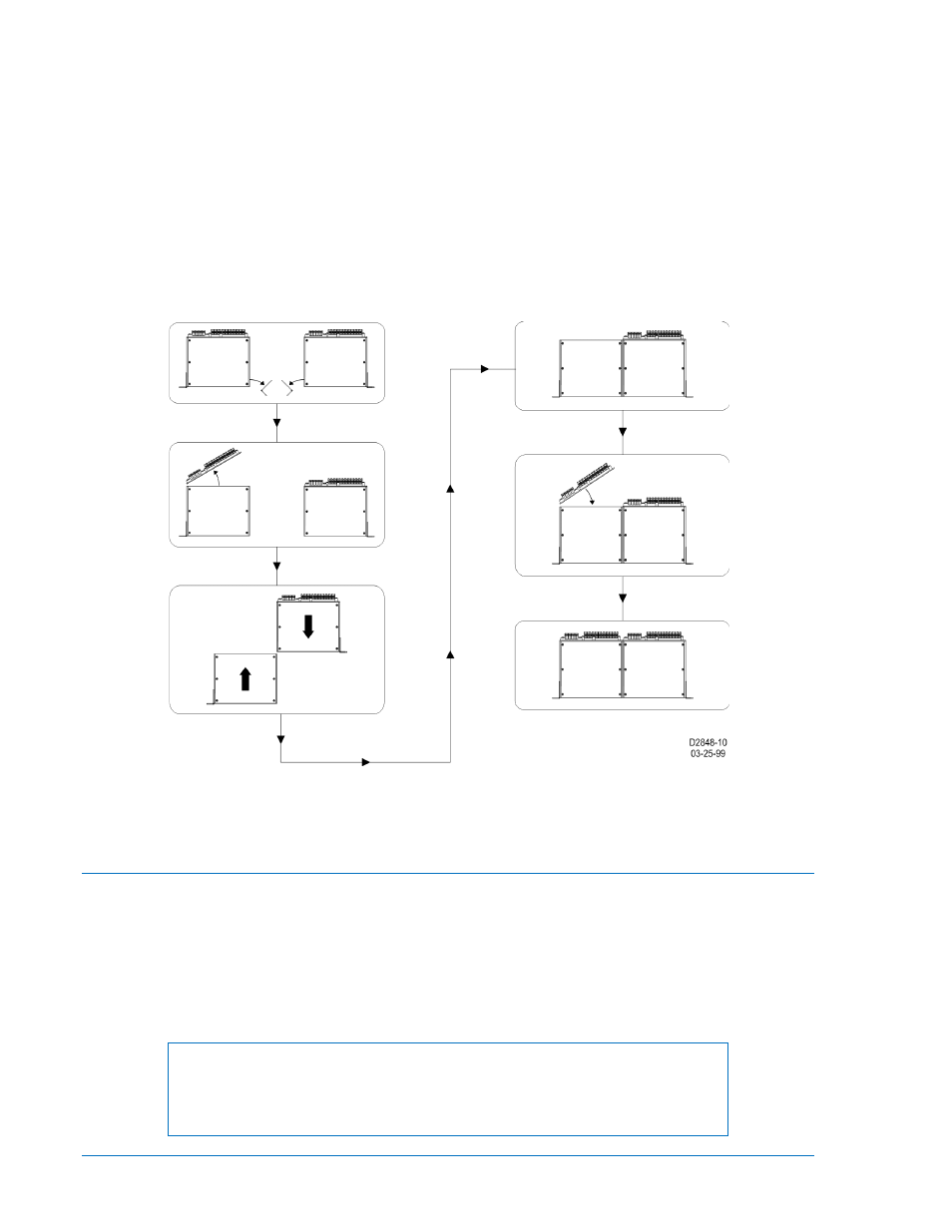
Step 6: Position the rear panel on the case from which it was removed. Make sure that the panel
orientation is correct. Perform Step 6a if Terminal Strip A was not removed during the
disassembly process. Perform Step 6b if Terminal Strip A was removed during disassembly.
Step 6a: Position the rear panel over the case and align the screw closest to Terminal Strip A with its
mating hole. Tighten the screw while maintaining proper alignment between the rear panel and
case. Finish attaching the panel to the case by installing the remaining three Phillips screws.
When installed, the rear panels prevent the two cases from sliding apart.
Step 6b: Align the rear panel with the case and install the four Phillips screws that hold the rear panel in
place. Position Terminal Strip A in its panel opening and replace the two Torx
T15 screws.
When installed, the rear panels prevent the two cases from sliding apart.
Step 7: Mount the case assembly in the desired rack or panel opening and reinstall the draw-out
assembly in each case.
Figure 12-15. Dovetailing Procedure Diagram
Relay Connections
Connections to the relay are dependent on the application and logic scheme selected by the user. As a
result, all of the relay's inputs and outputs may not be used for a given application. Before energizing a
relay, make sure the connections match the options associated with the model and style number found on
the relay nameplate. Refer to Figure 1-1, Style Chart, in Section 1, General Information, for available
options. Be sure to use the correct input power for the specified power supply. Incorrect wiring may result
in damage to the relay.
Figures 12-16, 12-17, and 12-18 are rear views of the F1, H1, and S1 style cases showing the terminal
connections.
NOTE
Depending upon the style number of the relay, the Alarm output contact may
be normally-closed (N.C.) or normally-open (N.O.). Verify the Alarm contact
configuration of your relay by referring to the style chart.
12-14
BE1-851 Installation
9289900990 Rev R