Basler Electric BE1-851 User Manual
Page 59
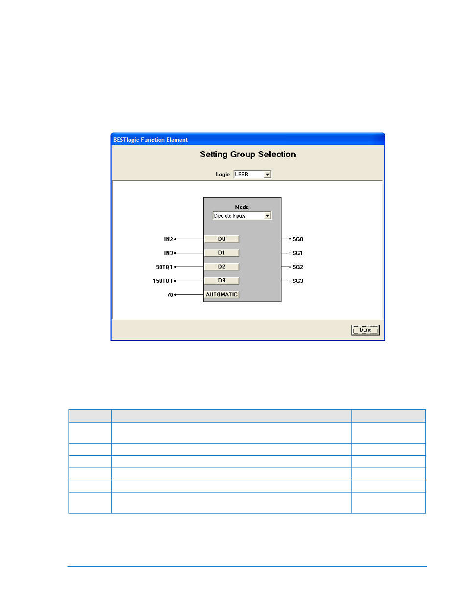
At the top center of the BESTlogic Function Element screen is a pull-down menu labeled Logic. This
menu allows viewing of the BESTlogic settings for each preprogrammed logic scheme. User must be
selected on this menu to allow changes to the mode and inputs of the function/element.
Enable the setting group control function by selecting its mode of operation from the Mode pull-down
menu. To connect the setting group control functions inputs, select the button for the corresponding input
in the BESTlogic Function Element screen. The BESTlogic Expression Builder screen will open. Select
the expression type to be used. Then, select the BESTlogic variable or series of variables to be
connected to the input. Select Save when finished to return to the BESTlogic Function Element screen.
For more details on the BESTlogic Expression Builder, see Section 7, BESTlogic Programmable Logic.
Select Done once the settings have been completely edited.
Figure 4-2. BESTlogic Function Element Screen, Setting Group Selection
Table 4-1 summarizes the BESTlogic settings for Setting Group Control. These settings will determine
how the function selects the active setting group when manual logic selection is enabled.
Table 4-1. BESTlogic Settings for Setting Group Control
Function
Range/Purpose
Default
Mode
0 = Disabled, 1 = Discrete Inputs, 2 = Binary Inputs (If Auto mode is
desired, logic mode must be either 1 or 2.)
1 (Discrete Inputs)
D0
Logic expression. Meaning is dependent upon the Mode setting.
0
D1
Logic expression. Meaning is dependent upon the Mode setting.
0
D2
Logic expression. Meaning is dependent upon the Mode setting.
0
D3
Logic expression. Meaning is dependent upon the Mode setting.
0
Automatic Logic Expression. When TRUE enables automatic control and when
FALSE enables logic control.
0
Manual (logic) control reads the status of the logic inputs to the setting group control function block to
determine what setting group should be active. For the logic inputs to determine which setting group
should be active, the AUTOMATIC input must be logic 0. The function block logic mode setting
determines how it reads these logic inputs. There are three possible logic modes as shown in Table 4-1.
9289900990 Rev R
BE1-851 Protection and Control
4-3