General, Contact-sensing input jumpers, Section 12 • installation -1 – Basler Electric BE1-851 User Manual
Page 263: General -1, Contact-sensing input jumpers -1, Table 12-1. contact-sensing turn-on voltages -1
SECTION 12 • INSTALLATION
General
BE1-851 Overcurrent Protection Systems are delivered with this instruction manual and BESTCOMS™
software in a sturdy carton to prevent shipping damages. Upon receipt of the relay, check the model and
style number against the requisition and packaging list for agreement. Inspect for damage and if there is
evidence of such, immediately file a claim with the carrier and notify the Basler Electric Regional Sales
Office, your sales representative, or a sales representative at Basler Electric, Highland, Illinois.
If the relay is not installed immediately, store it in the original shipping package in a moisture and dust
free environment.
Contact-Sensing Input Jumpers
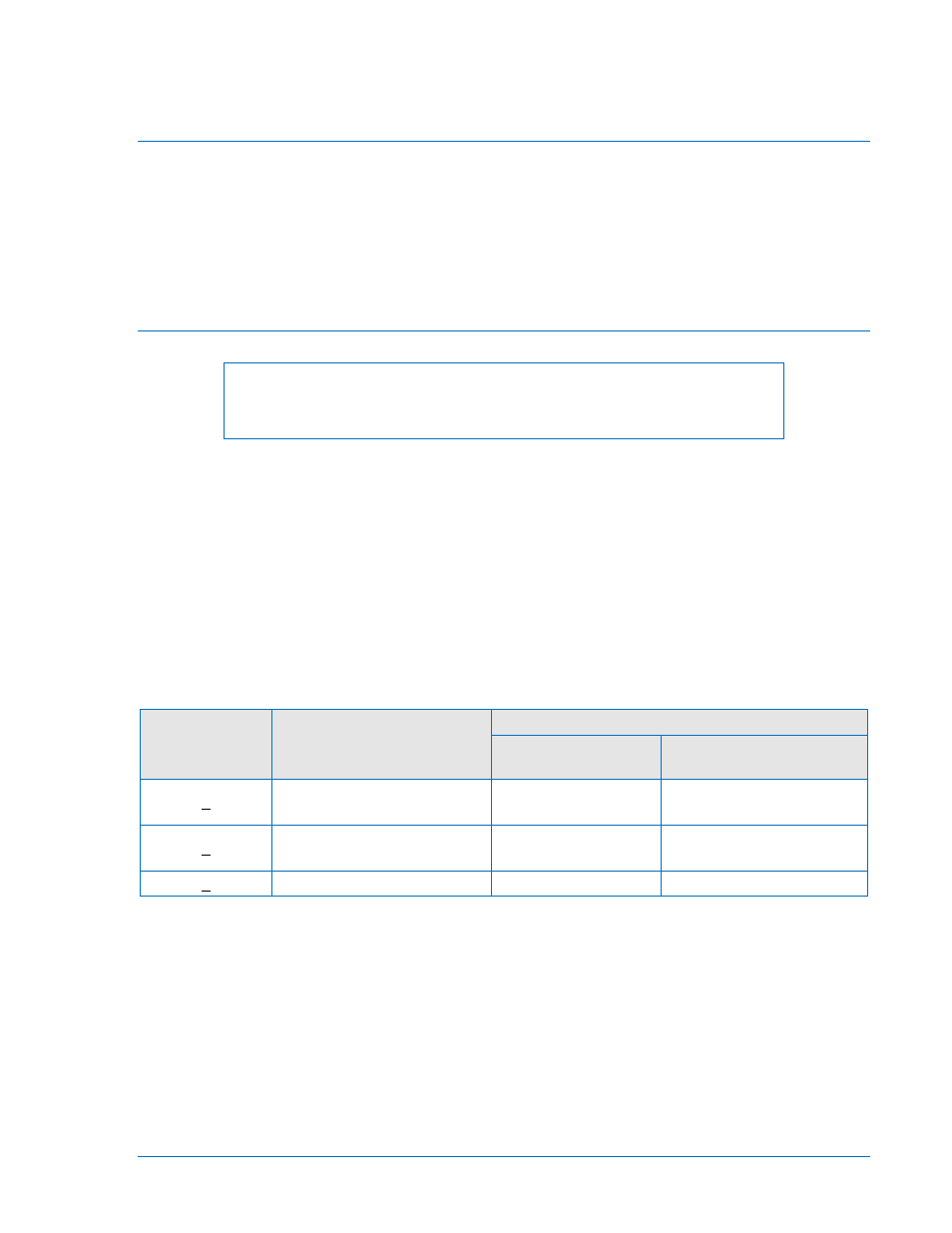
NOTE
The BE1-851 relay is delivered with the jumpers in the HIGH position. Read
the following paragraphs closely before placing the relay in service.
Four contact-sensing inputs provide external stimulus to initiate BE1-851 actions. An external wetting
voltage is required for the contact-sensing inputs. The nominal voltage level of the external dc source
must comply with the dc power supply input voltage ranges listed in Section 1, General Information,
General Specifications. To enhance user flexibility, the BE1-851 uses wide range ac/dc power supplies
that cover several common control voltages. The contact-sensing input circuits are designed to respond
to voltages at the lower end of the control voltage range while not overheating at the high end of the
range.
Energizing levels for the contact-sensing inputs are jumper selectable for a minimum of approximately
5 Vdc for 24 Vdc nominal sensing voltages, 26 Vdc for 48 Vdc nominal sensing voltages, or 69 Vdc for
125 Vdc nominal sensing voltages. See Table 12-1 for the contact-sensing turn-on voltages.
Table 12-1. Contact-Sensing Turn-On Voltages
Style Option
Nominal Input Voltage
Contact-Sensing Turn-On Voltage *
Jumper Installed
(Low Position)
Jumper Not Installed
(High Position)
xxx1xxx
48 Vdc or 125 Vac/dc
26 to 38 Vdc
69 to 100 Vdc
56 to 97 Vac
xxx2xxx
125/250 Vac/dc
69 to 100 Vdc
56 to 97 Vac
138 to 200 Vdc
112 to 194 Vac
xxx3xxx
24 Vdc
n/a
Approx. 5 Vdc
*
AC voltage ranges are calculated using the default recognition time (4 ms) and debounce time (16 ms).
Each BE1-851 is delivered without the contact-sensing jumpers installed for operation in the higher end of
the control voltage range. If the contact-sensing inputs are to be operated at the lower end of the control
voltage range, the jumpers must be installed.
The following describes how to locate and remove/change the contact sensing input jumpers:
1. Remove the draw-out assembly by loosening the two thumbscrews and pulling the assembly out
of the case. Observe all electrostatic discharge (ESD) precautions when handing the draw-out
assemble.
2. Locate the two jumper blocks that are mounted on the Digital Circuit Board. The Digital Circuit
Board is the middle board in the assembly and the jumper terminal blocks are located on the
component side of the circuit board. Each terminal block has two sets of pins. With the jumper as
9289900990 Rev R
BE1-851 Installation
12-1