Entering passwords, Performing control operations, Entering passwords -9 – Basler Electric BE1-851 User Manual
Page 239: Performing control operations -9, Figure 10-10. virtual control switch 143 screen -9
details on entering passwords from the HMI. Once access has been gained, the Edit LED will be
lighted and a cursor will appear in the first settings field on the screen.
3. Press the UP or DOWN scrolling key to select the desired setting. Some settings require entering
a number one character at a time. For example, to enter a 51 pickup as 7.3 amps, you would
press the UP pushbutton until the 7 is showing. Then, press the RIGHT pushbutton to move the
cursor over and press the UP pushbutton until the “
.” is showing. Then press the RIGHT
pushbutton to move the cursor over and press the UP pushbutton until the 3 is showing. Other
settings require scrolling through a list of selections. For example, you would move the cursor over
to the CRV field and then scroll through a list of available TCC curves.
4. Once all of the settings on the screen have been entered, press the Edit pushbutton a second time
and the settings will be validated. If the settings are in range, the screen will flash
CHANGES
SAVED, and the Edit LED will go out. If you want to abort the edit session without changing any
settings, press the Reset pushbutton before you press the Edit pushbutton the second time. The
screen will flash
CHANGES LOST and the Edit LED will go out.
Entering Passwords
If password security has been initiated for a function, the HMI will prompt you to enter a password when
the Edit pushbutton is pressed. To gain access, you must enter the appropriate password. A field of eight
asterisks appears with the cursor located under the leftmost character position. You can enter passwords
by performing the following procedure:
1. Press the UP or DOWN scrolling pushbuttons until the proper first character of the password
appears. Pressing the UP pushbutton scrolls through the alphabet and then the numbers in
ascending order. Pressing DOWN scrolls through the numbers and then the alphabet in
descending order.
2. Press the RIGHT scrolling pushbutton to move the cursor to the next character of the password
and select the appropriate character.
3. Continue the process until the entire password has been spelled out. If the password is less than
eight characters, leave the remaining asterisks in place instead of entering blanks.
4. Press the Edit pushbutton to enter the password. If the proper password has been entered, the
screen will flash
ACCESS GRANTED. If an incorrect password has been entered, the screen will
flash
ACCESS DENIED and the Edit LED will go out.
5. Once you gain access, it remains in effect for five minutes. As long as you continue to press the
Edit key for a function for which you have gained access, the five-minute timer will be refreshed
and you will not be prompted for a password.
Performing Control Operations
Control operations can be executed at Menu Branch 2, CONTROL of the HMI LCD. These functions allow
you to control the state of virtual switches, override logic, control the active setting group, and control the
state of output contacts. All of these functions work similarly to the process of entering settings in that you
press the Edit pushbutton for the action to be executed.
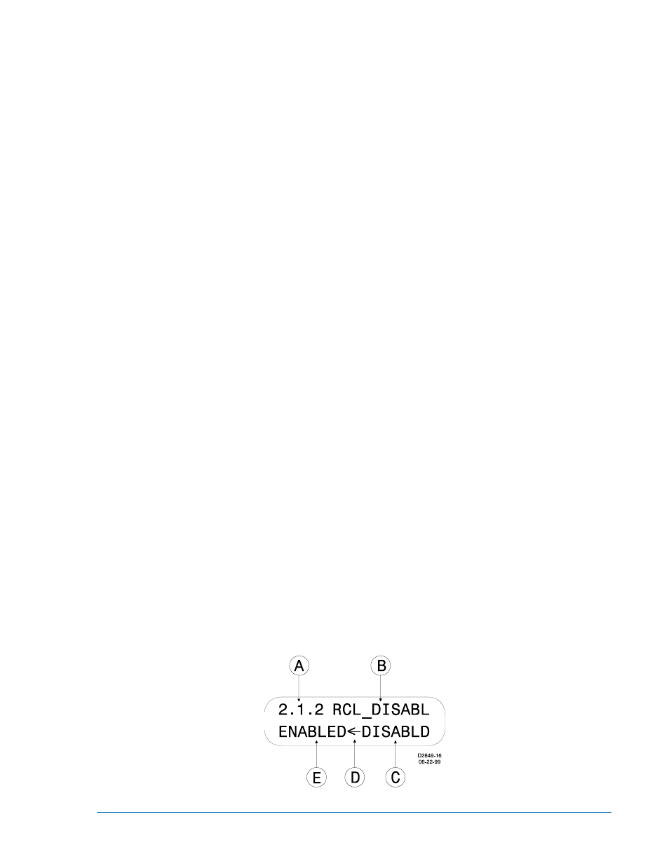
Figure 10-10 shows Virtual Switch 143 as an example of a virtual switch screen. See Section 4,
Protection and Control, for more details on the x43 and 101 functions. Table 10-3 describes each of the
locators shown on Figure 10-10. The user programmable label for this switch has been set to
RCL_DISABL. The TRUE (closed) state label has been set to DISABLD. The FALSE (open) state label
has been set to ENABLED. The logical mode for this application would be set to Mode 2 (On/Off switch).
Figure 10-10. Virtual Control Switch 143 Screen
9289900990 Rev R
BE1-851 Human-Machine Interface
10-9