Figure 8-19. output seal-in logic diagram -65, Table 8-30. output contact seal-in logic -65 – Basler Electric BE1-851 User Manual
Page 221
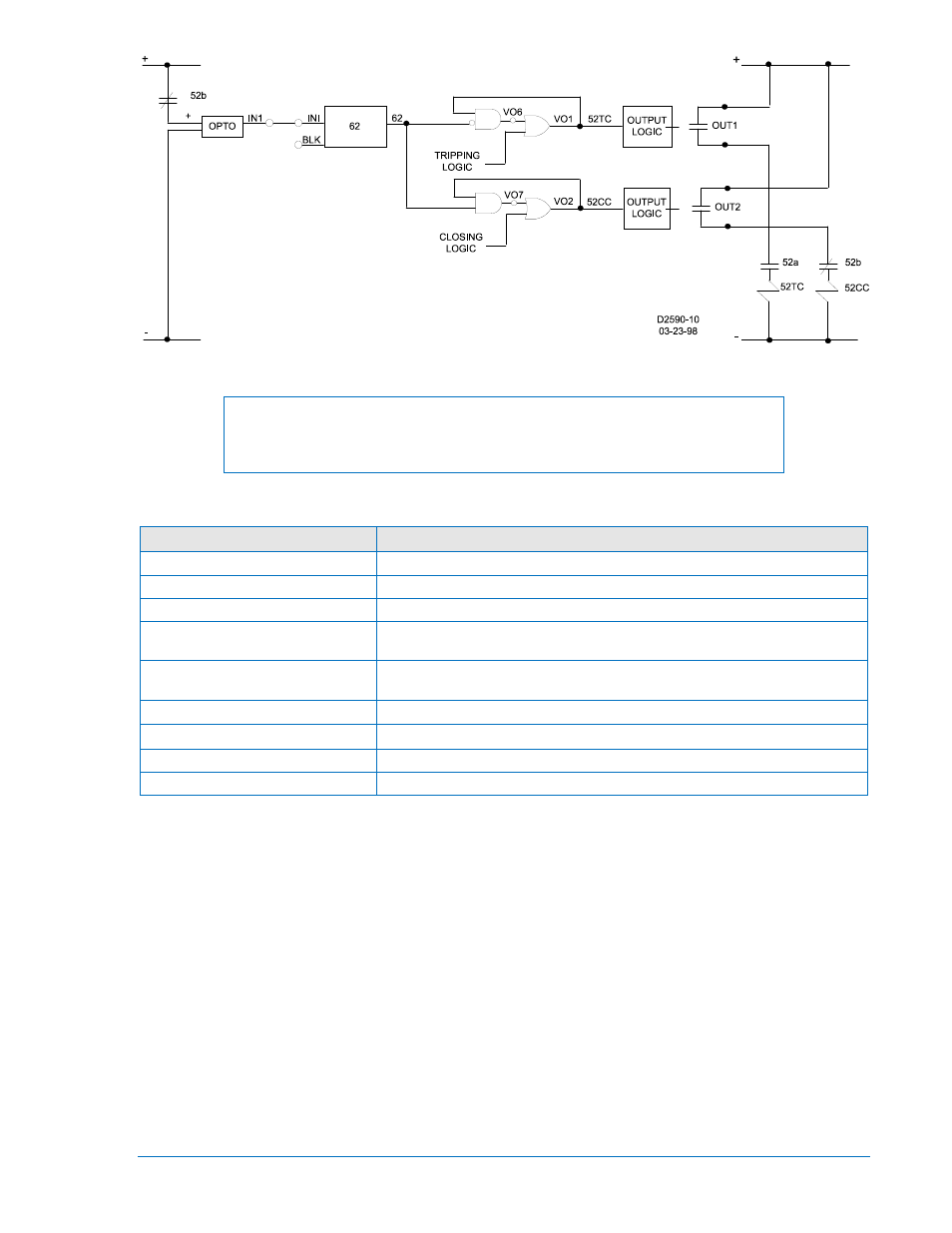
Figure 8-19. Output Seal-In Logic Diagram
NOTE
This example is based on the Feeder_2, Feeder_3, or Feeder_4
preprogrammed logic schemes.
Table 8-30. Output Contact Seal-In Logic
Command
Purpose
SG-HOLD1=0
Turn off the hold timer for output 1.
SL-62=1,IN1,0
Set the timer logic to mode 1 (pickup/dropout), IN1 to initiate, no blocking.
S#-62=2c,2c
Set the pickup (2 cycles) and dropout (2 cycles) times.
VO1=101T+BFPU+VO11+VO6*/62 Set the tripping logic for breaker control switch trip or breaker fail pickup or
virtual output 11 or virtual output 6 and not 62.
VO2=101C+79C+VO7*62
Set the closing logic for breaker control switch close or79 close or virtual
output 7 and 62.
VO6=VO1∗/62
Set the virtual output 6 logic to VO1 and not 62.
VO7=VO2∗62
Set the virtual output 7 logic to VO2 and 62.
E
Exit.
Y
Save settings.
Oscillographic Recording of Breaker Closures and Openings
How do I program the relay to create an oscillographic record when the breaker closes or opens? Monitor
the circuit breaker status by connecting the 52b contacts to IN1. Set a general-purpose logic timer (62) for
Mode 1 (Pickup/Dropout), initiated by not input one (/IN1) and no blocking with T1 equal to 0.15 seconds,
and T2 equal to 0.015 seconds (SL-62=1,?in1,0 and S<#>-62=0.015,0.015). Program a virtual output
(VO10) to be TRUE (high) when the input to IN1is FALSE and the 62 output is False or when the IN1
input is TRUE and the 62 Output is TRUE (VO10=/IN1*/62+IN1*62). Set the SG-TRIGGER command for
a logic trigger when VO10 is TRUE (SG-TRIGGER=
Here is the scenario: The breaker has been open for a while. Therefore, IN1 input is TRUE and the 62
Output is FALSE. When the breaker closes, the IN1 input becomes FALSE and because the 62 Output is
FALSE, Virtual Output 10 goes TRUE for the duration of T1 (15 milliseconds). After the T1 time delay, the
62 Output goes TRUE and remains TRUE until the initiate input (IN1) goes FALSE for the duration of T2.
Virtual Output 10 was TRUE for the 15 milliseconds time delay of T1 and triggered the oscillographic
record when the breaker closed.
Before the breaker opens, IN1 if FALSE and the 62 output is TRUE. When the breaker opens, IN1
becomes TRUE longer than time delay T2. During that time T2, Virtual Output 10 is TRUE because both
IN1 and the 62 Output are TRUE because both IN1 and the 62 Output are TRUE. This time, an
oscillographic record is triggered because the circuit breaker opened.
9289900990 Rev R
BE1-851 Application
8-65