Table 13-24. command settings -11, Table 13-25. timing ranges -11, Table 13-26. command settings -11 – Basler Electric BE1-851 User Manual
Page 299
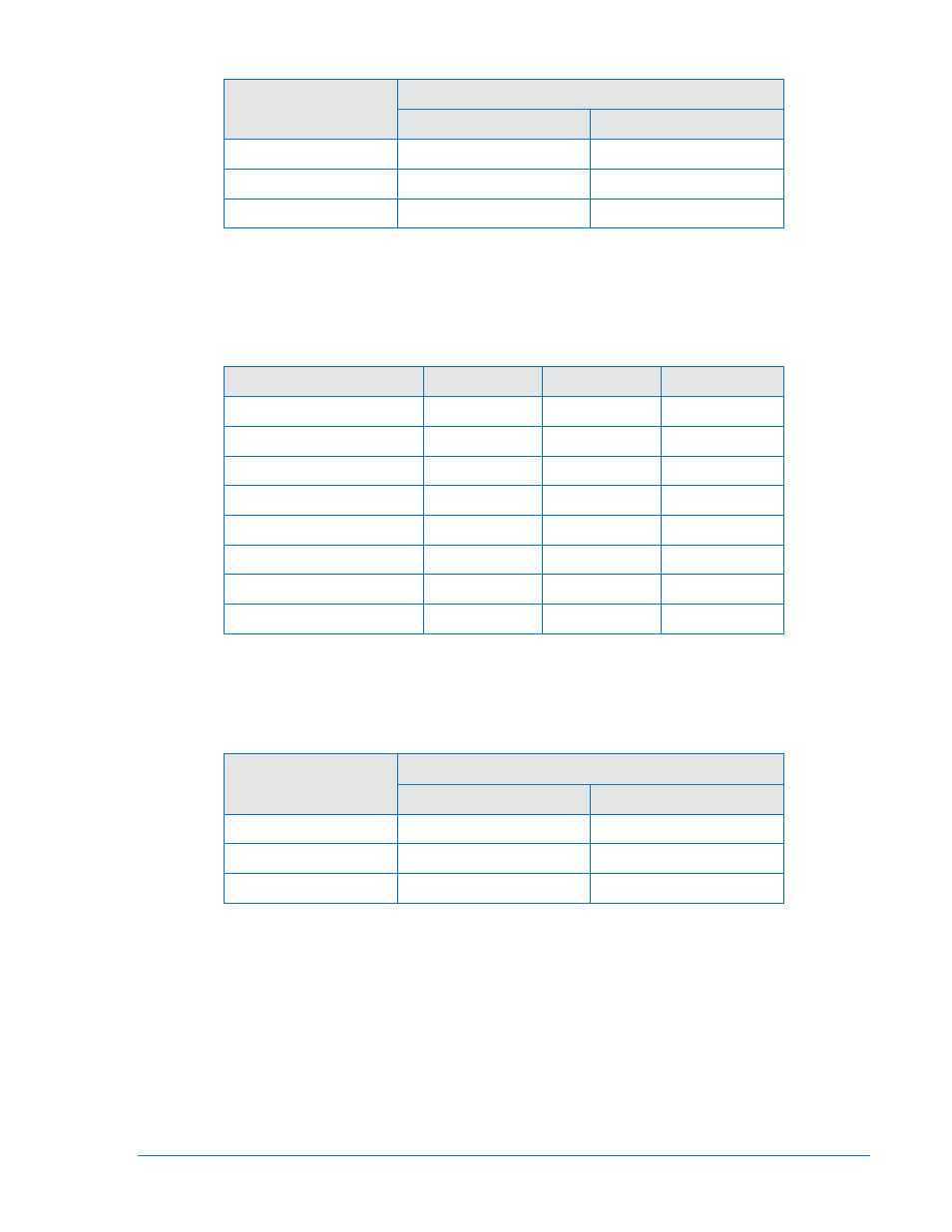
Table 13-24. Command Settings
Style Number
Commands
Phase
Neutral
x1xxxxx
S0-51P=0.1A,5.0,I2
S0-51N=0.1A,5.0,I2
x3xxxxx
S0-51P=0.5A,5.0,I2
S0-51N=0.1A,5.0,I2
x5xxxxx
S0-51P=0.5A,5.0,I2
S0-51N=0.5A,5.0,I2
Step 5:
Apply the appropriate current value to the Phase A current input and measure the time
between the application of current and OUT1 closing. Verify that the timing is within the
acceptance range stated in Table 13-25.
Table 13-25. Timing Ranges
Style Number
Current
Low Limit
High Limit
x1xxxxx
0.2 amps
4.205 sec
4.647 sec
x1xxxxx
1.0 amps
1.272 sec
1.405 sec
x1xxxxx
2.6 amps
0.935 sec
1.033 sec
x1xxxxx
4.0 amps
0.846 sec
0.934 sec
x3xxxxx or x5xxxxx
1.0 amps
4.205 sec
4.647 sec
x3xxxxx or x5xxxxx
5.0 amps
1.272 sec
1.405 sec
x3xxxxx or x5xxxxx
13.0 amps
0.935 sec
1.033 sec
x3xxxxx or x5xxxxx
20.0 amps
0.846 sec
0.934 sec
Step 6:
Transmit the appropriate command from Table 13-26 to reprogram the pickup, time delay
setting, and curve type.
Table 13-26. Command Settings
Style Number
Commands
Phase
Neutral
x1xxxxx
S0-51P=0.1A,9.9,I2
S0-51N=0.1A,9.9,I2
x3xxxxx
S0-51P=0.5A,9.9,I2
S0-51N=0.1A,9.9,I2
x5xxxxx
S0-51P=0.5A,9.9,I2
S0-51N=0.5A,9.9,I2
Step 7:
Apply the appropriate current value to the Phase A current input and measure the time
between the application of current and OUT1 closing. Verify that the timing is within the
acceptance range stated in Table 13-27.
9289900990 Rev R
BE1-851 Testing and Maintenance
13-11