2 digital inputs, 6wiring, 7 control element – Pilz PMCprimo DriveP.01/AA0/4/0/0/208-480VAC User Manual
Page 126
6.7
Control element
6
Wiring
Pilz GmbH & Co. KG, Felix-Wankel-Straße 2, 73760 Ostfildern, Germany
Telephone: +49 711 3409-0, Telefax: +49 711 3409-133, E-Mail: [email protected]
6-22
6.7.2
Digital inputs
Digital inputs
6-
][Verdr_Leiterquerschnitte_Verweis
Under “Connection cables”, please note the requirements for the:
`
Cable cross sections
`
Insulation material
][Verdr_DI_protego_D
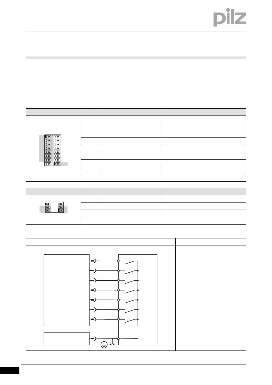
Connector pin assignment
Connector X3A/X3B
Pin
Designation
Description
1
ENABLE
Enable input
2
DIGITAL-IN1
Digital input 1
3
DIGITAL-IN2
Digital input 2
4
DIGITAL-IN3
Digital input 3
5
DIGITAL-IN4
Digital input 4
6
DIGITAL-INOUT 1
Digital input or output 1
7
DIGITAL-INOUT 2
Digital input or output 2
16
DGND
Reference earth for digital inputs and outputs
Connector X4A/X4B
Pin
Designation
Description
3
STO2-ENABLE
STO – Safe torque off, 2nd shutdown route
2, 5
XGND
Reference earth for 24 VDC
6
STO1-ENABLE
STO – Safe torque off, 1st shutdown route
Connection
Input circuit
Digital input
24 VDC
Referenced to earth: Always connect
DGND (X3B/16) to I/O-GND on the
control system
PSTOP, NSTOP: Evaluation of limit
switch
Pin 6 and 7 is configured as a digital
input in the commissioning software
X3A
1
2
3
4
X3B
5
6
7
8
9
10
12
13
14
15
16
11
X4A
1
2
X4B
4
5
3
6
NSTOP
1
ENABLE
DIGITAL-IN1
2
3
4
DGND
5
PMCprotego
24 V
I/O-GND
X3A
DIGITAL-INOUT1
DIGITAL-IN4
DIGITAL-IN3
DIGITAL-IN2
DIGITAL-INOUT2
6
7
X3B
16
ENABLE
PSTOP
- PMCprimo DriveP.01/AA0/5/0/0/208-480VAC PMCprimo DriveP.12/AA0/4/0/0/208-480VAC PMCprimo DriveP.12/AA0/4/P/0/208-480VAC PMCprimo DriveP.03/AA0/4/0/0/208-480VAC PMCprimo DriveP.06/AA0/4/0/0/208-480VAC PMCprimo DriveP.24/ABB/4/0/0/208-480VAC PMCprimo DriveP.03/AB0/5/0/0/208-480VAC PMCprimo DriveP.06/AB0/2/0/0/208-480VAC PMCprimo DriveP.03/AB0/3/0/0/208-480VAC PMCprimo DriveP.06/AB0/3/0/0/208-480VAC PMCprimo DriveP.12/AB0/2/0/0/208-480VAC PMCprimo DriveP.12/ABC/4/P/0/208-480VAC PMCprimo DriveP.12/AB0/3/0/0/208-480VAC PMCprimo DriveP.03/AB0/2/0/0/208-480VAC PMCprimo DriveP.12/AAC/4/0/0/208-480VAC PMCprimo DriveP.24/AA0/5/0/0/208-480VAC PMCprimo DriveP.12/AA0/2/0/0/208-480VAC PMCprotego D.01/000/0/0/2/208-480VAC PMCprotego D.03/000/0/0/2/208-480VAC PMCprotego D.06/000/0/0/2/208-480VAC PMCprotego D.12/000/0/0/2/208-480VAC PMCprotego D.24/000/0/0/2/208-480VAC PMCprotego D.12/000/0/P/2/208-480VAC PMCprotego D.24/000/0/P/2/208-480VAC PMCprotego D.01/200/0/0/2/208-480VAC PMCprotego D.01/100/0/0/2/208-480VAC PMCprotego D.01/010/0/0/2/208-480VAC PMCprotego D.06/010/0/0/2/208-480VAC PMCprotego D.06/100/0/0/2/208-480VAC PMCprotego D.06/200/0/0/2/208-480VAC PMCprotego D.03/010/0/0/2/208-480VAC PMCprotego D.03/200/0/0/2/208-480VAC PMCprotego D.03/100/0/0/2/208-480VAC PMCprotego D.12/010/0/0/2/208-480VAC PMCprotego D.24/200/0/P/2/208-480VAC PMCprotego D.12/200/0/0/2/208-480VAC PMCprotego D.12/100/0/0/2/208-480VAC PMCprotego D.12/010/0/P/2/208-480VAC PMCprotego D.12/200/0/P/2/208-480VAC PMCprotego D.24/100/0/P/2/208-480VAC PMCprotego D.24/010/0/P/2/208-480VAC PMCprotego D.12/100/0/P/2/208-480VAC PMCprotego D.24/200/0/0/2/208-480VAC PMCprotego D.24/100/0/0/2/208-480VAC PMCprotego D.24/010/0/0/2/208-480VAC