Align transmitter, 7commissioning, 2 initial commissioning – Pilz PSENvip RL D P User Manual
Page 90
7.2
Initial commissioning
7
Commissioning
Pilz GmbH & Co. KG, Felix-Wankel-Straße 2, 73760 Ostfildern, Germany
Telephone: +49 711 3409-0, Telefax: +49 711 3409-133, E-Mail: [email protected]
7-6
7.2.1.4
Align transmitter
Align transmitter
7-
Inbetriebnahme_Erstinbetriebnahme_Sender_ausrichten
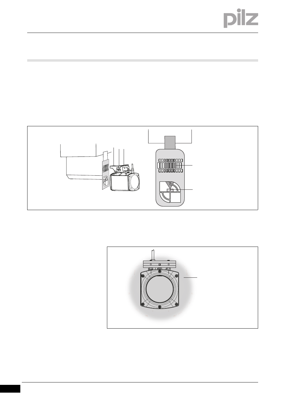
Attach an adjustment template with magnets to the upper tool. The tip
of the upper tool must sit in the notch on the stop of the adjustment
template.
Align the alignment grid of the adjustment template to the contour of
the upper tool.
Fig. 7-4:
Attach the adjustment template to the transmitter
The illuminated target area must completely envelop the receiver. If
you hold a white sheet of paper behind the receiver you will be able
to see the contours of the receiver better.
Fig. 7-5:
Receiver illuminated by transmitter
If the illuminated target area does not enclose the receiver as shown
in the diagram, then you will need to realign the transmitter
Align the
alignment grid
on the upper
tool
Centre point of
the upper tool
in the notch on
the back stop
Illuminated target area