Adjustment templates, 7commissioning, 2 initial commissioning – Pilz PSENvip RL D P User Manual
Page 87
Pilz GmbH & Co. KG, Felix-Wankel-Straße 2, 73760 Ostfildern, Germany
Telephone: +49 711 3409-0, Telefax: +49 711 3409-133, E-Mail: [email protected]
7-3
7.2
Initial commissioning
7
Commissioning
7.2.1.2
Adjustment templates
Adjustment templates
7-
Inbetriebnahme_Erstinbetriebnahme_Justageschablonen
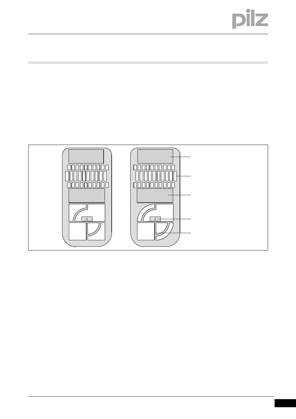
Two adjustment templates and the information on the display provide
support when aligning the transmitter and receiver.
Please note the different cut-outs around the cross-hair on the two ad-
justment templates. On the left-hand adjustment template in the illustra-
tion below, the cross-hair is located within a square cutout. The different
forms make it easier to secure information about the direction of move-
ment when aligning the transmitter and receiver.
Fig. 7-1:
Adjustment templates (viewed from the magnet side)
You can select either adjustment template to attach to the transmitter or
receiver side.
Magnet
Alignment grid
Magnet
Back gauge with notch
Cross-hair