Pin assignment, 10 system connections, 1 overview – Pilz PSENvip RL D P User Manual
Page 138
10.1
Overview
10
System Connections
Pilz GmbH & Co. KG, Felix-Wankel-Straße 2, 73760 Ostfildern, Germany
Telephone: +49 711 3409-0, Telefax: +49 711 3409-133, E-Mail: [email protected]
10-8
10.1.2
Pin assignment
Pin assignment
10-
Systemanbindung_Uebersicht_Anschluesse
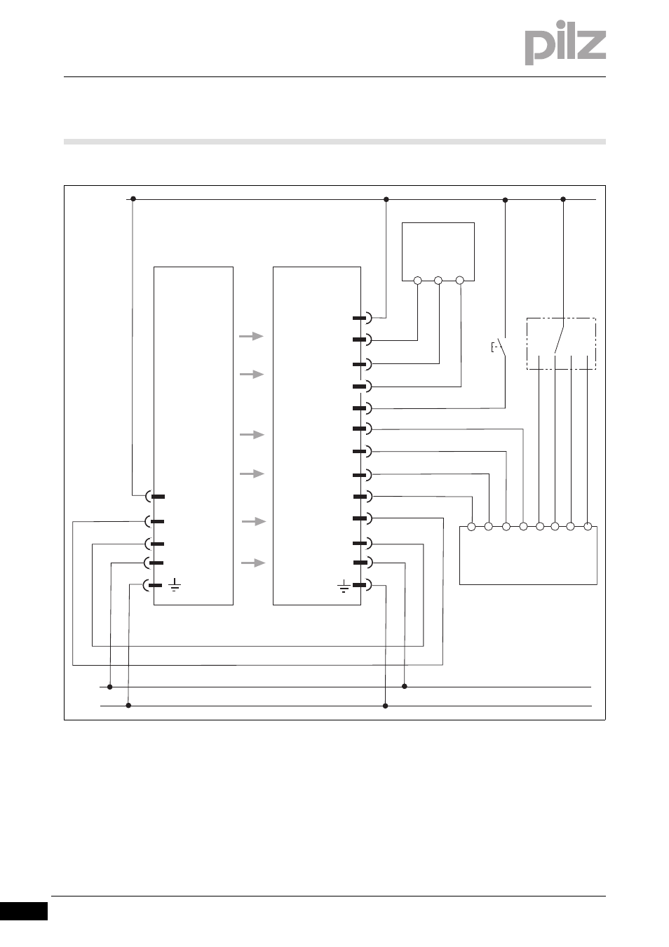
Fig. 10-1:
Connecting the PSENvip to a programmable safety system
Key:
S1: Pushbutton to reset protected field mode
S2: Operating mode selector switch for protected field mode
PSENvip
Receiver
PSENvip
Transmitter
OSSD 2
24 VDC
OSSD 1
TRM_ON
TRM_SYNC
TRM_ON
TRM_SYNC
24 VDC
0 V
24 VDC
0 V
0 V
PE
Protected
field mode 1
Overrun mea-
surement 2
I0 I1 I2 I3 I 4 I 5 I6
O0 O1
PSS
PNOZmulti
PSS
PNOZmulti
I7
S1
S2
Reset
Protected
field mode 2
Overrun mea-
surement 1
Power Off
O2
This manual is related to the following products: