6wiring, 2 connections – Pilz PSENvip RL D P User Manual
Page 81
Pilz GmbH & Co. KG, Felix-Wankel-Straße 2, 73760 Ostfildern, Germany
Telephone: +49 711 3409-0, Telefax: +49 711 3409-133, E-Mail: [email protected]
6-5
6.2
Connections
6
Wiring
*) Used in communication between PSENvip and safety system.
Pin assignment of M12 connector X2 on the receiver
*) Used in communication between PSENvip and safety system.
Verdrahtung_Anschluss_Empfänger_OSSD
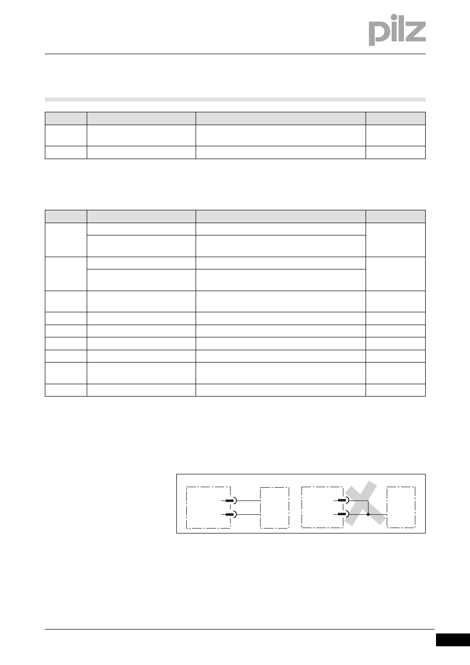
The two safety outputs OSSD1 and OSSD2 must be connected sepa-
rately to the machine's programmable safety system. OSSD1 and
OSSD2 must not be connected.
Fig. 6-4:
Correct and incorrect connection of OSSD1 and OSSD2
8
TRM_ON
Output, signal to switch the transmitter's light
source on and off
Red
Shield
Cable shield
PIn No.
Designation
Description
Colour
1
Overrun measurement 2
Output, result of overrun measurement
White
Tool class PSENvip -> PLC Bit 2
*)
Output, sends tool class Bit 2 to safety system
2
Power Off
Input, activates setup mode
Brown
PLC Ready *)
Input, safety system signals that it is ready for com-
munication
3
Acknowledgement
Input, acknowledges initiation of a press stroke with
reduced protected field
Green
4
System-Init
Input, the press is at top dead centre
Yellow
5
OSSD2
Output, OSSD2
Grey
6
Acknowledge PSENvip -> PLC *) Output, confirm validity of tool class
Pink
7
0 V
Input, 0 V supply voltage
Blue
8
TRM_SYNC
Output, signal to control the intensity of the trans-
mitter's light source
Red
Shield
Cable shield
PIn No.
Designation
Description
Colour
OSSD2
OSSD1
OSSD2
OSSD1