Pnozmulti, 10 system connections, 3 pnozmulti – Pilz PSENvip RL D P User Manual
Page 142
10.3
PNOZmulti
10
System Connections
Pilz GmbH & Co. KG, Felix-Wankel-Straße 2, 73760 Ostfildern, Germany
Telephone: +49 711 3409-0, Telefax: +49 711 3409-133, E-Mail: [email protected]
10-12
10.3
PNOZmulti
10300
PNOZmulti
10-
Systemanbindung_PNOZmulti
The following example illustrates a user program in the PNOZmulti Con-
figurator.
For the sake of clarity, the wiring diagram does not show the PNOZmulti
supply voltage nor any other signals (see "Overview" section).
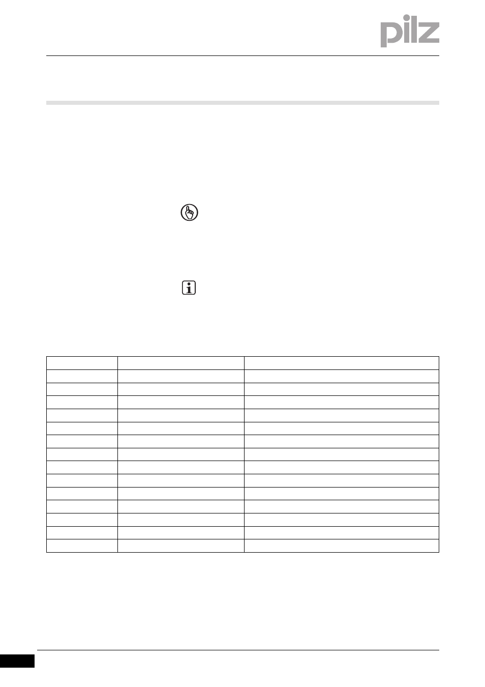
10.3.1
Configuration of the inputs and outputs (e.g. PNOZ m1p)
Configuration of the inputs and outputs (e.g. PNOZ m1p)
10-
Systemanbindung_PNOZmulti_Belegung
NOTICE
Please refer to the safety guideline given in the "Overview" sec-
tion in this chapter.
INFORMATION
For a description of the user program please refer to the
PNOZmulti Configurator's online help.
Input/Output
Designation
Description
A1.i0
OSSD1
OSSD1 output on the PSENvip
A1.i1
OSSD2
OSSD2 output on the PSENvip
A1.i2
Overrun_Channel1
Overrun measurement output 1 on the PSENvip
A1.i3
Overrun_Channel2
Overrun measurement output 2 on the PSENvip
A1.i4
Standard
Standard protected field mode
A1.i5
Box
Box bending protected field mode
A1.i6
Backgauge
Back gauge protected field mode
A1.i7
Box_Backgauge
Box bending with back gauge protected field mode
A1.i9
Safety_Speed
Safe speed = creep speed signal
A1.i10
PSENvip_Guard_On
Switches the Power Off input on the PSENvip
A1.o0
Protection_Mode1
Protected field mode input 1 on the PSENvip
A1.o1
Protection_Mode2
Protected field mode input 2 on the PSENvip
A1.o2
PSENvip_Off
Power Off input on the PSENvip
A1.o3
Overrun_End
Signals the end of the overrun measurement