6wiring – Pilz PSENvip RL D P User Manual
Page 78
6.1
Notes on wiring
6
Wiring
Pilz GmbH & Co. KG, Felix-Wankel-Straße 2, 73760 Ostfildern, Germany
Telephone: +49 711 3409-0, Telefax: +49 711 3409-133, E-Mail: [email protected]
6-2
Verdrahtung_Hinweise_EMV
EMC
Avoid interference (e.g. from motors, power lines) by laying cables in
a way that is EMC-compliant.
Verdrahtung_Hinweise_Eingaenge_des_Empfaengers
Inputs on the receiver
The inputs Protected field mode 1/Protected field mode 2 are safe-
ty-related.
– The CNC or safety system provides the signal. It is only absolutely
necessary to connect the inputs to a safety system if communica-
tion is needed for tool detection.
– When driven via relay contacts it is the user's responsibility to apply
an appropriate safety concept.
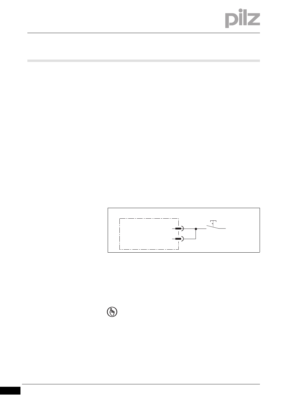
The inputs for protected field mode 1 and protected field mode 2 can
be switched directly via the 24 VDC supply. In this case, both inputs
should be linked. Only the following protected field modes are pos-
sible:
– "Standard" protected field mode (switch open, both inputs = "0")
– "Box bending with back gauge" protected field mode (switch
closed, both inputs = "1")
Fig. 6-1:
Protected field mode 1/2 directly at the 24 V DC supply
The input to acknowledge the specified protected field mode can be
switched directly via the 24 VDC supply.
Verdrahtung_Hinweise_Funktionspruefung
NOTICE
The acknowledgement button for the protected field mode must
be positioned outside the danger zone in such a way that the
operator can see all of the danger zone.
Protected field mode 2
Protected field mode 1
X1
3
4
24 V DC