Transmitter, Supply voltage, Connection between transmitter and receiver – Pilz PSENvip RL D P User Manual
Page 82: 6wiring, 2 connections, 2 transmitter, 3 supply voltage, 4 connection between transmitter and receiver
6.2
Connections
6
Wiring
Pilz GmbH & Co. KG, Felix-Wankel-Straße 2, 73760 Ostfildern, Germany
Telephone: +49 711 3409-0, Telefax: +49 711 3409-133, E-Mail: [email protected]
6-6
6.2.2
Transmitter
Transmitter
6-
Funktion_Geraete_Sender_Stecker
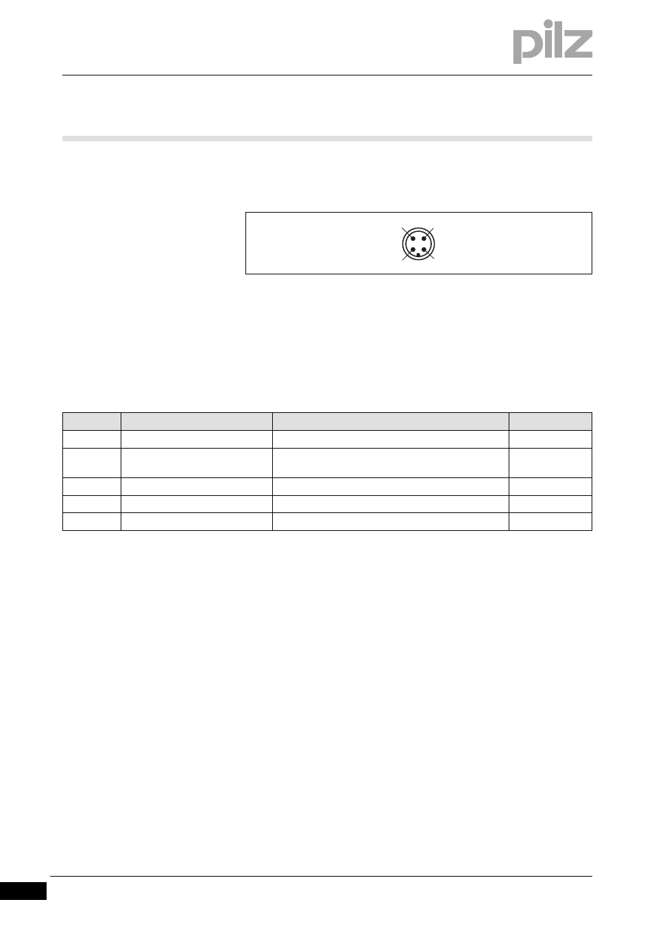
The top of the transmitter has a 4-pin M12 connector.
Verdrahtung_Anschluss_Sender
Fig. 6-5:
Pin assignment of transmitter
The transmitter is connected via a 4-core cable. The cable ends of the
Pilz ready-made cable are colour-coded. Please refer to the table below
for the coding details.
Pin assignment of M12 connector X3 on the transmitter
6.2.3
Supply voltage
Supply voltage
6-
Verdrahtung_Anschluss_Versorgungsspannung
The supply voltage is fed to the receiver and transmitter via the 8-core /
4-core connection cable.
6.2.4
Connection between transmitter and receiver
Connection between transmitter and receiver
6-
Verdrahtung_Anschluss_Verbildung_Sender_Empfaenger
The signals TRM_ON and TRM_SYNC are routed via the control cabinet.
Pin no.
Designation
Description
Colour
1
24 V DC
Input, 24 V DC supply voltage
brown
2
TRM_SYNC
Input, signal to control the intensity of the light
source
white
3
0 V
Input, 0 V supply voltage
blue
4
TRM_ON
Input, signal to switch the light source on and off
Black
Shield
Cable shielding
1
2
3
4