Preface – Rockwell Automation 1761 MicroLogix 1000 Programmable Controllers User Manual
Page 306
Preface
MicroLogix 1000 Programmable Controllers User Manual
B–18
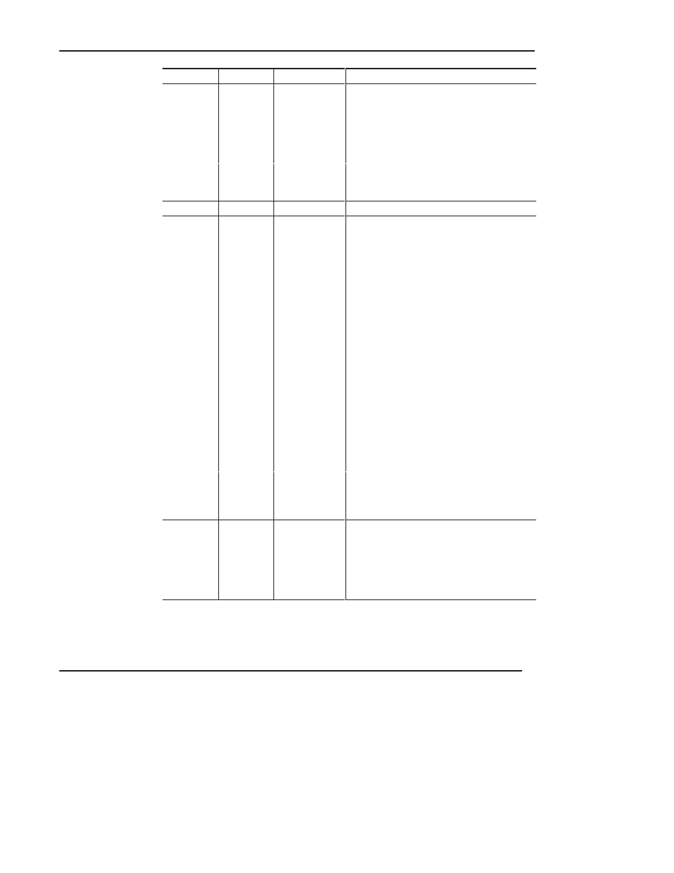
Address
Bit
Classification
Description
S:7
Suspend
Code
Status
When a non-zero value appears in S:7, it
indicates that the SUS instruction identified by
this value has been evaluated as true, and the
Suspend Idle mode is in effect. This pinpoints
the conditions in the application that caused the
Suspend Idle mode. This value is not cleared by
the controller.
Use the SUS instruction with startup
troubleshooting, or as runtime diagnostics for
detection of system errors.
S:8 to S:12
Reserved
NA
NA
S:13 and
S:14
Math
Register
Status
Use this double register to produce 32-bit signed
divide and multiply operations, precision divide or
double divide operations, and 5-digit BCD
conversions.
These two words are used in conjunction with the
MUL, DIV, DDV, FRD, and TOD math
instructions. The math register value is assessed
upon execution of the instruction and remains
valid until the next MUL, DIV, DDV, FRD, or TOD
instruction is executed in the user program.
An explanation of how the math register operates
is included with the instruction definitions.
If you store 32-bit signed data values, you must
manage this data type without the aid of an
assigned 32-bit data type. For example, combine
B3:0 and B3:1 to create a 32-bit signed data
value. We recommend that you start all 32-bit
values on an even or odd word boundary for
ease of application and viewing. Also, we
recommend that you design, document, and view
the contents of 32-bit signed data in either the
hexadecimal or binary radix.
When an STI, high-speed counter, or Fault
Routine interrupts normal execution of your
program, the original value of the math register is
restored when execution resumes.
S:15L
DF1 Node
Address
Status
This byte value contains the node address of
your processor on the DF1 link. It is used when
executing Message (MSG) instructions over the
DF1 link. The default node address of a
processor is 1. Valid node addresses are 0–254.
To change a processor node address you must
use a programming device.