Programming – Rockwell Automation 1761 MicroLogix 1000 Programmable Controllers User Manual
Page 139
Using Math Instructions
8–7
(U)
S:5
0
END
] [
B3
0
[OSR]
B3
1
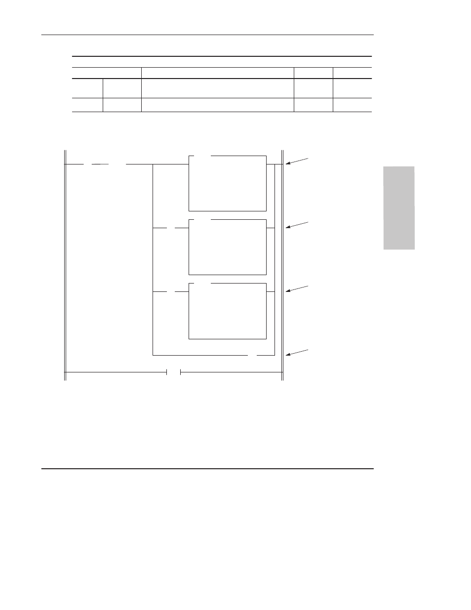
When the rung goes
true for a single scan,
B3:1 is added to B3:2.
The result is placed in
B3:2.
SUB
SUBTRACT
Source A
B3:3
0000000000000011
Source B
1
Dest
B3:3
0000000000000011
ADD
ADD
Source A
B3:1
0101010110101000
Source B
B3:2
0001100101000000
Dest
B3:2
0001100101000000
ADD
ADD
Source A
1
Source B
B3:3
0000000000000011
Dest
B3:3
0000000000000011
] [
S:0
0
] [
B3
31
Add 16–bit value B3:1 to 32–bit value B3:3 B3:2
Add Operation
Binary
Hex
Decimal
B3:3 B3:2
B3:1
B3:3 B3:2
0000 0000 0000 0011 0001 1001 0100 0000
0101 0101 1010 1000
0000 0000 0000 0011 0110 1110 1110 1000
0003 1940
55A8
0003 6EE8
203,072
21,928
225,000
Addend
Addend
Sum
➀
If a carry is generated
(S:0/0 set), 1 is added
to B3:3.
If B3:1 is negative
(B3/31 set), 1 is
subtracted from B3:3.
Overflow trap bit
S:5/0 is unlatched to
prevent a major error
from occurring at the
end of the scan.
➀
The programming device displays 16-bit decimal values only. The decimal value of a 32-bit integer is derived
from the displayed binary or hex value. For example, 0003 1940 Hex is 16
4
x3 + 16
3
x1 + 16
2
x9 + 16
1
x4 + 16
0
x0
= 203,072.
Programming
- 20P PowerFlex DC Drive - Frame D Bimetal Thermostat (10 pages)
- 1336S_F_T_E_R F Frame Snubber Resistor Repl. (6 pages)
- 22-COMM PowerFlex 4-Class DSI (Drive Serial Interface) Network Communication Adapter (4 pages)
- 8-545 Plug In Solid State Relay (2 pages)
- 20-HIM-B1 PowerFlex 7-Class HIM Bezel (DPI) (4 pages)
- 100 Contactors with DC Coil (1 page)
- 100 Contactors with DC Coil (2 pages)
- 20P PowerFlex DC Drive - Frame D Switching Power Supply Circuit Board (6 pages)
- 140G-MTFx_MTHx_MTIx_MTKx Trip Unit Installation-140G-M (6 pages)
- 45BRD Analog Laser Sensor (4 pages)
- 20D Multi-Device Interface Option Board for PowerFlex 700S Drives (20 pages)
- 56RF RFID 18 mm Cylindrical Transceiver (2 pages)
- 42KC Miniature Rectangular: 5V DC Version (2 pages)
- 20P PowerFlex DC Drive - Frame A Switching Power Supply Circuit Board (16 pages)
- 21P-MISC-A-TP-2 Transition Tube Kit #C19-6/7 For PowerFlex 755 w/OEM Liquid Cooling Fr 6/7 Drive (2 pages)
- 42BT Background Suppression Sensor (3 pages)
- 42CB High Speed 18mm Cylindrical (4 pages)
- 140EX-JE2_JE3 Molded Case Circuit Breaker (4 pages)
- 140G-K-EAM1A Early Make Aux Contact for Rotary Handle Oper Mech-140G-K (1 page)
- 140G-K-EAM1A Early Make Aux Contact for Rotary Handle Oper Mech-140G-K (3 pages)
- 20-HIM-A6 PowerFlex (Human Interface Module) (74 pages)
- 42CF General Purpose 12mm Cylindrical (4 pages)
- 20D PowerFlex 700S Phase II Drive Frames 1...6 (80 pages)
- 140EX-HE1_HE2 Molded Case Circuit Breaker (6 pages)
- 140EX-HE1_HE2 Molded Case Circuit Breaker (4 pages)
- 20B PowerFlex 700 Custom Firmware - Pump Off (12 pages)
- 20-WIM-N4S DPI Wireless Interface Module (92 pages)
- 140U H-Frame Circuit Breaker Fixed and Adjustable Thermal Trip (7 pages)
- 140U H-Frame Circuit Breaker Fixed and Adjustable Thermal Trip (2 pages)
- 60-2619, 42JS Swivel/Tilt Mounting Bracket (1 page)
- 22A PowerFlex 4/40/400 Flange Mount (4 pages)
- 45MLA Controller Installation Instructions (16 pages)
- 20P PowerFlex DC Drive - Cooling Fan for Frame A Drives Above 73A at 230V 460V AC (6 pages)
- 42JS Series 7000 to 42JS VisiSight Replacement Kit (2 pages)
- 22A PowerFlex 4-Class HIM Bezel (DSI) (4 pages)
- 42CS Stainless Steel Photoelectric Sensors (4 pages)
- 20L-LL PowerFlex 700L Liquid-to-Liquid Heat Exchanger (40 pages)
- 20P PowerFlex DC Drive - Frame B SCR Modules (20 pages)
- 22B PowerFlex 40 Quick Start FRN 5.xx - 6.xx (161 pages)
- 22B PowerFlex 40 Quick Start FRN 5.xx - 6.xx (22 pages)
- 22F PowerFlex 4M Input RFI Filters (2 pages)
- 45LFM Capacitive Label Sensor (4 pages)
- 140G-Rx Installation Instruction-140G-R (2 pages)
- 140G-Rx Installation Instruction-140G-R (29 pages)
- 22C PowerFlex 400 AC Drive Quick Start - FRN 1-4.xx (28 pages)