Rockwell Automation 1761 MicroLogix 1000 Programmable Controllers User Manual
Page 267
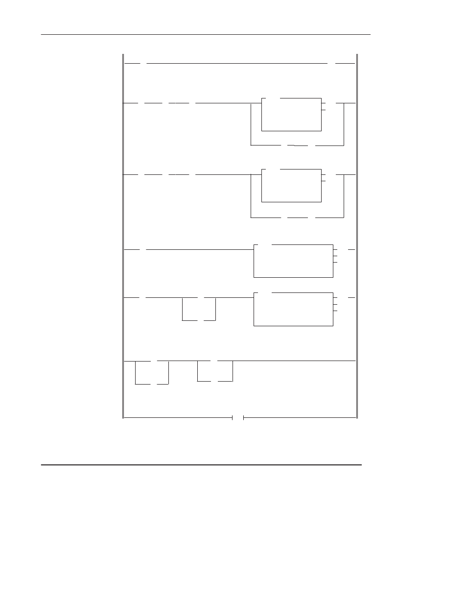
Using the Message Instruction
13–19
END
2.0
]/[
N7:0
12
(EN)
(DN)
TON
TIMER ON DELAY
Timer
T4:0
Time Base
0.01
Preset
600
Accum
0
(L)
N7:0
] [
N7:0
15
] [
T4:0
DN
2.1
2.2
2.5
2.6
2.4
8
(U)
N7:0
15
]/[
N7:0
13
]/[
N7:20
12
] [
N7:20
15
]/[
N7:20
13
(EN)
(DN)
TON
TIMER ON DELAY
Timer
T4:1
Time Base
0.01
Preset
600
Accum
0
(L)
N7:20
] [
T4:1
DN
8
2.3
] [
N7:0
12
(EN)
(DN)
(ER)
MSG
READ/WRITE MESSAGE
Read/write
READ
Target Device
SLC500/ML1000
Control Block
N7:20
Control Block Length
7
] [
N7:0
13
] [
N7:20
12
] [
N7:20
13
This rung starts messaging each REM Run or RUN mode entry by clearing the EN bit of the first MSG instruction.
Same as above rung.
This rung sets the timeout value. (When using a SLC 5/03 or SLC 5/04 processor, this rung and rung 2:2 are not
required because you can enter the value 6 into the Timeout value field in the MSG instruction block.)
The MSG instruction energizes upon entry into the REM Run or RUN mode. No input conditions are required.
The MSG instruction is energized when the previous MSG instruction completes.
This rung resets all MSG instructions when the last MSG instruction has completed.
(EN)
(DN)
(ER)
MSG
READ/WRITE MESSAGE
Read/write
WRITE
Target Device
SLC500/ML1000
Control Block
N7:0
Control Block Length
7
] [
S:1
15
] [
S:0
11
] [
S:0
11
(U)
N7:0
15
N7:20
(U)
15
- 20P PowerFlex DC Drive - Frame D Bimetal Thermostat (10 pages)
- 1336S_F_T_E_R F Frame Snubber Resistor Repl. (6 pages)
- 22-COMM PowerFlex 4-Class DSI (Drive Serial Interface) Network Communication Adapter (4 pages)
- 8-545 Plug In Solid State Relay (2 pages)
- 20-HIM-B1 PowerFlex 7-Class HIM Bezel (DPI) (4 pages)
- 100 Contactors with DC Coil (1 page)
- 100 Contactors with DC Coil (2 pages)
- 20P PowerFlex DC Drive - Frame D Switching Power Supply Circuit Board (6 pages)
- 140G-MTFx_MTHx_MTIx_MTKx Trip Unit Installation-140G-M (6 pages)
- 45BRD Analog Laser Sensor (4 pages)
- 20D Multi-Device Interface Option Board for PowerFlex 700S Drives (20 pages)
- 56RF RFID 18 mm Cylindrical Transceiver (2 pages)
- 42KC Miniature Rectangular: 5V DC Version (2 pages)
- 20P PowerFlex DC Drive - Frame A Switching Power Supply Circuit Board (16 pages)
- 21P-MISC-A-TP-2 Transition Tube Kit #C19-6/7 For PowerFlex 755 w/OEM Liquid Cooling Fr 6/7 Drive (2 pages)
- 42BT Background Suppression Sensor (3 pages)
- 42CB High Speed 18mm Cylindrical (4 pages)
- 140EX-JE2_JE3 Molded Case Circuit Breaker (4 pages)
- 140G-K-EAM1A Early Make Aux Contact for Rotary Handle Oper Mech-140G-K (1 page)
- 140G-K-EAM1A Early Make Aux Contact for Rotary Handle Oper Mech-140G-K (3 pages)
- 20-HIM-A6 PowerFlex (Human Interface Module) (74 pages)
- 42CF General Purpose 12mm Cylindrical (4 pages)
- 20D PowerFlex 700S Phase II Drive Frames 1...6 (80 pages)
- 140EX-HE1_HE2 Molded Case Circuit Breaker (6 pages)
- 140EX-HE1_HE2 Molded Case Circuit Breaker (4 pages)
- 20B PowerFlex 700 Custom Firmware - Pump Off (12 pages)
- 20-WIM-N4S DPI Wireless Interface Module (92 pages)
- 140U H-Frame Circuit Breaker Fixed and Adjustable Thermal Trip (7 pages)
- 140U H-Frame Circuit Breaker Fixed and Adjustable Thermal Trip (2 pages)
- 60-2619, 42JS Swivel/Tilt Mounting Bracket (1 page)
- 22A PowerFlex 4/40/400 Flange Mount (4 pages)
- 45MLA Controller Installation Instructions (16 pages)
- 20P PowerFlex DC Drive - Cooling Fan for Frame A Drives Above 73A at 230V 460V AC (6 pages)
- 42JS Series 7000 to 42JS VisiSight Replacement Kit (2 pages)
- 22A PowerFlex 4-Class HIM Bezel (DSI) (4 pages)
- 42CS Stainless Steel Photoelectric Sensors (4 pages)
- 20L-LL PowerFlex 700L Liquid-to-Liquid Heat Exchanger (40 pages)
- 20P PowerFlex DC Drive - Frame B SCR Modules (20 pages)
- 22B PowerFlex 40 Quick Start FRN 5.xx - 6.xx (161 pages)
- 22B PowerFlex 40 Quick Start FRN 5.xx - 6.xx (22 pages)
- 22F PowerFlex 4M Input RFI Filters (2 pages)
- 45LFM Capacitive Label Sensor (4 pages)
- 140G-Rx Installation Instruction-140G-R (2 pages)
- 140G-Rx Installation Instruction-140G-R (29 pages)
- 22C PowerFlex 400 AC Drive Quick Start - FRN 1-4.xx (28 pages)