Preface, Operation – Rockwell Automation 1761 MicroLogix 1000 Programmable Controllers User Manual
Page 202
Preface
MicroLogix 1000 Programmable Controllers User Manual
11–14
Status bits of the control structure include:
–
Error Bit ER (bit 11) is set when the controller detects a negative
position value, or a negative or zero length value. When the ER bit is set,
the minor error bit (S5:2) is also set. Both bits must be cleared.
–
Done Bit DN (bit 13) is set after the instruction has operated on the last
word in the sequencer load file. It is reset on the next false-to-true rung
transition after the rung goes false.
–
Enable Bit EN (bit 15) is set on a false-to-true transition of the SQL rung
and reset on a true-to-false transition.
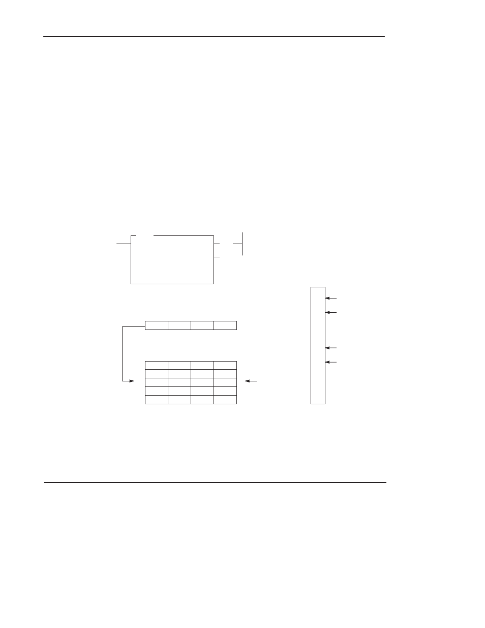
Operation
Instruction parameters have been programmed in the SQL instruction shown below.
Input word I:0.0 is the source. Data in this word is loaded into integer file #N7:30
by the sequencer load instruction.
(EN)
(DN)
SQL
SEQUENCER LOAD
File
#N7:30
Source
I:0.0
Control
R6:4
Length
4
Position
2
0000
0101
0000
1010
0
7
8
15
0000
0000
0000
0000
1010
0010
1111
0101
0000
0101
0000
1010
0000
0000
0000
0000
0000
0000
0000
0000
0
1
2
3
4
Step
N7:30
31
32
33
34
Word
00
01
02
03
04
05
06
07
08
09
10
11
12
13
14
15
ON
ON
ON
ON
External Inputs
Associated with I:0.0
Source I:0.0
Sequencer Load File #N7:30
Current Step
When rung conditions change from false-to-true, the SQL enable bit (EN) is set.
The control element R6:4 increments to the next position in the sequencer file, and
loads the contents of source I:0.0 into the corresponding location in the file. The
SQL instruction continues to load the current data into this location each scan that
the rung remains true. When the rung goes false, the enable bit (EN) is reset.