Rockwell Automation 1761 MicroLogix 1000 Programmable Controllers User Manual
Page 263
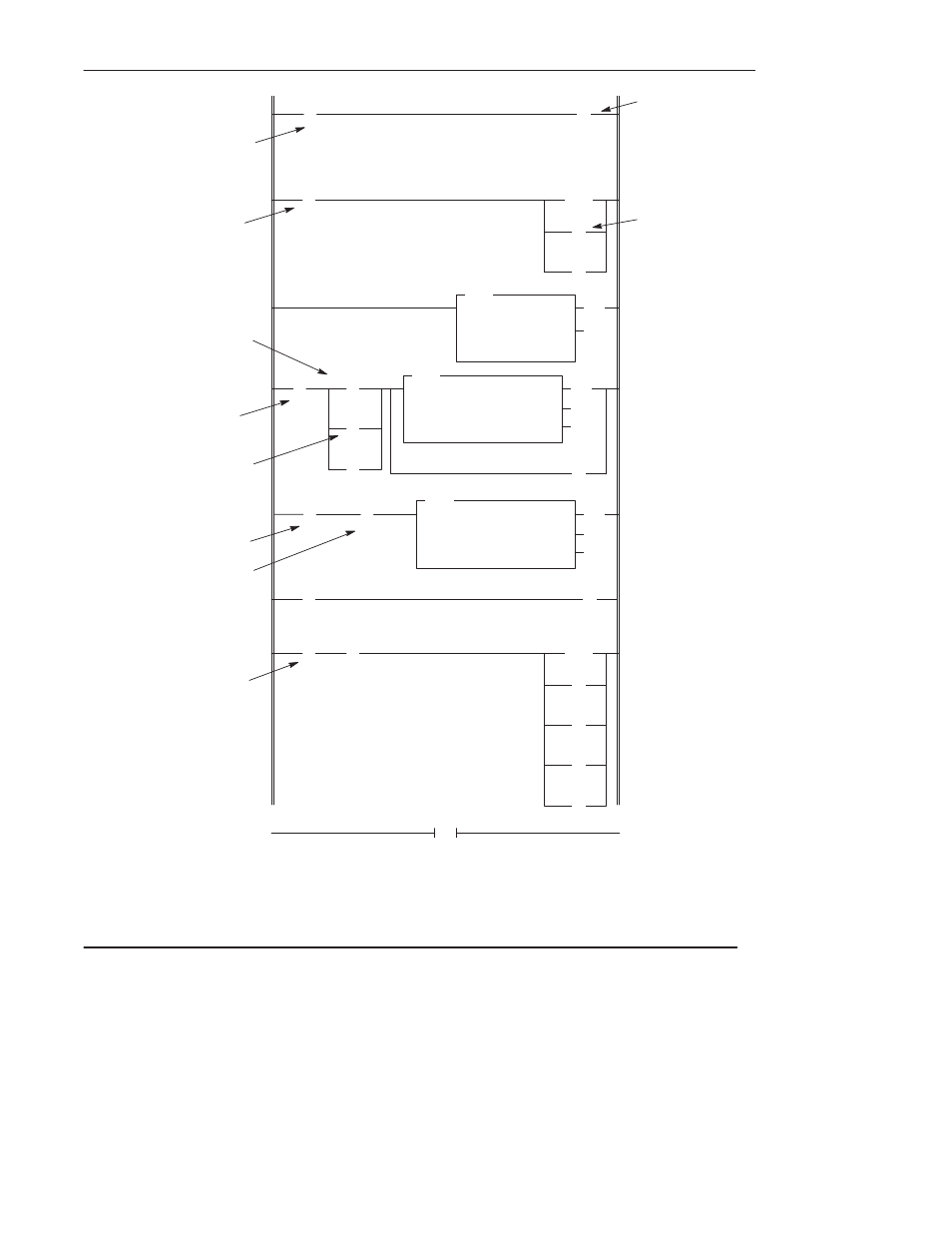
Using the Message Instruction
13–15
(U)
B3
0
(EN)
(DN)
(ER)
MSG
READ/WRITE MESSAGE
Read/write
WRITE
Target Device
SLC500/ML1000
Control Block
N7:10
Control Block Length
7
END
0
2
* MSG instruction
status bits:
13 = DN
15 = EN
]/[
N7:0
0
(L)
B3
0
( )
N7:0
1
(RES)
T4:0
(EN)
(DN)
TON
TIMER ON DELAY
Timer
T4:0
Time Base
0.01
Preset
400
Accum
0
Temperature-sensing
Input Device
S:1
15
] [
S:4
6
3
] [
B3
0
(L)
N7:0
0
] [
S:1
15
] [
S:0
11
(EN)
(DN)
(ER)
MSG
READ/WRITE MESSAGE
Read/write
READ
Target Device
SLC500/ML1000
Control Block
N7:21
Control Block Length
7
] [
N7:10
13*
] [
T4:0
DN
] [
N7:21
13*
(U)
B3
0
(RES)
T4:0
(U)
N7:0
0
(U)
N7:21
(U)
N7:10
15*
Operation notes appear on the following page.
4
5
6
7
Bit 1 of the message
word. Used for fan
control.
Bit 0 of the
message word.
This is the interlock
bit.
4-second Timer
Write message
instruction. The source
and target file addresses
are N7:0
Target node: 3
Message length: 1 word.
Read message
instruction. The
destination and target file
addresses are N7:0
Target node: 3
Message length: 1 word.
Latch – This alarm
instruction notifies the
application if the
interlock bit N7:0/0
remains set for more
than 4 seconds.
First Pass Bit
First Pass Bit
1280 ms Clock Bit
Message Write
Done Bit
Message Read
Done Bit
1
(L)
B3
10
] [
I:1.0
5
DH-485 Active
Protocol Bit
] [
S:0
11
DH-485 Active
Protocol Bit
] [
15*
- 20P PowerFlex DC Drive - Frame D Bimetal Thermostat (10 pages)
- 1336S_F_T_E_R F Frame Snubber Resistor Repl. (6 pages)
- 22-COMM PowerFlex 4-Class DSI (Drive Serial Interface) Network Communication Adapter (4 pages)
- 8-545 Plug In Solid State Relay (2 pages)
- 20-HIM-B1 PowerFlex 7-Class HIM Bezel (DPI) (4 pages)
- 100 Contactors with DC Coil (2 pages)
- 100 Contactors with DC Coil (1 page)
- 20P PowerFlex DC Drive - Frame D Switching Power Supply Circuit Board (6 pages)
- 140G-MTFx_MTHx_MTIx_MTKx Trip Unit Installation-140G-M (6 pages)
- 45BRD Analog Laser Sensor (4 pages)
- 20D Multi-Device Interface Option Board for PowerFlex 700S Drives (20 pages)
- 56RF RFID 18 mm Cylindrical Transceiver (2 pages)
- 42KC Miniature Rectangular: 5V DC Version (2 pages)
- 20P PowerFlex DC Drive - Frame A Switching Power Supply Circuit Board (16 pages)
- 21P-MISC-A-TP-2 Transition Tube Kit #C19-6/7 For PowerFlex 755 w/OEM Liquid Cooling Fr 6/7 Drive (2 pages)
- 42BT Background Suppression Sensor (3 pages)
- 42CB High Speed 18mm Cylindrical (4 pages)
- 140EX-JE2_JE3 Molded Case Circuit Breaker (4 pages)
- 140G-K-EAM1A Early Make Aux Contact for Rotary Handle Oper Mech-140G-K (1 page)
- 140G-K-EAM1A Early Make Aux Contact for Rotary Handle Oper Mech-140G-K (3 pages)
- 20-HIM-A6 PowerFlex (Human Interface Module) (74 pages)
- 42CF General Purpose 12mm Cylindrical (4 pages)
- 20D PowerFlex 700S Phase II Drive Frames 1...6 (80 pages)
- 140EX-HE1_HE2 Molded Case Circuit Breaker (6 pages)
- 140EX-HE1_HE2 Molded Case Circuit Breaker (4 pages)
- 20B PowerFlex 700 Custom Firmware - Pump Off (12 pages)
- 20-WIM-N4S DPI Wireless Interface Module (92 pages)
- 140U H-Frame Circuit Breaker Fixed and Adjustable Thermal Trip (2 pages)
- 140U H-Frame Circuit Breaker Fixed and Adjustable Thermal Trip (7 pages)
- 60-2619, 42JS Swivel/Tilt Mounting Bracket (1 page)
- 22A PowerFlex 4/40/400 Flange Mount (4 pages)
- 45MLA Controller Installation Instructions (16 pages)
- 20P PowerFlex DC Drive - Cooling Fan for Frame A Drives Above 73A at 230V 460V AC (6 pages)
- 42JS Series 7000 to 42JS VisiSight Replacement Kit (2 pages)
- 22A PowerFlex 4-Class HIM Bezel (DSI) (4 pages)
- 42CS Stainless Steel Photoelectric Sensors (4 pages)
- 20L-LL PowerFlex 700L Liquid-to-Liquid Heat Exchanger (40 pages)
- 20P PowerFlex DC Drive - Frame B SCR Modules (20 pages)
- 22B PowerFlex 40 Quick Start FRN 5.xx - 6.xx (161 pages)
- 22B PowerFlex 40 Quick Start FRN 5.xx - 6.xx (22 pages)
- 22F PowerFlex 4M Input RFI Filters (2 pages)
- 45LFM Capacitive Label Sensor (4 pages)
- 140G-Rx Installation Instruction-140G-R (2 pages)
- 140G-Rx Installation Instruction-140G-R (29 pages)
- 22C PowerFlex 400 AC Drive Quick Start - FRN 1-4.xx (28 pages)