Current carrying capacity, 00 . 25 current carrying capacity – Northern Connectors Harting HAN Industrial Rectangular Connectors User Manual
Page 31
Han
00
.
25
Current carrying capacity
Current carrying capacity
The current carrying capacity is determined in tests which are
conducted on the basis of the DIN EN 60 512-5-2. The current
carrying capacity is limited by the thermal properties of materials
which are used for inserts as well as by the insulating materials.
These components have a limiting temperature which should not
be exceeded.
The relationship between the current, the temperature rise (loss
at the contact resistance) and the ambient temperature of the
connector is represented by a curve. On a linear coordinate system
the
current lies on the vertical line (ordinate) and the
ambient
temperature on the horizontal line (abscissa) which ends at the
upper limiting temperature.
In another measurement the self-heating (
∆
t) at different currents
is determined.
At least 3 points are determined which are connected to a parabolic
curve, the basic curve.
The corrected current carrying capacity curve is derived from this
basic curve. The reasons for the correction are external factors
that bring an additional limitation to the current carrying capacity,
i.e. connectable wire gauge or an unequal dispersion of current.
The derating diagrams pictured as curve have been primarily
determined with tin-plated cables as well as with physical cross
sections close to the respective ISO-cable cross section.
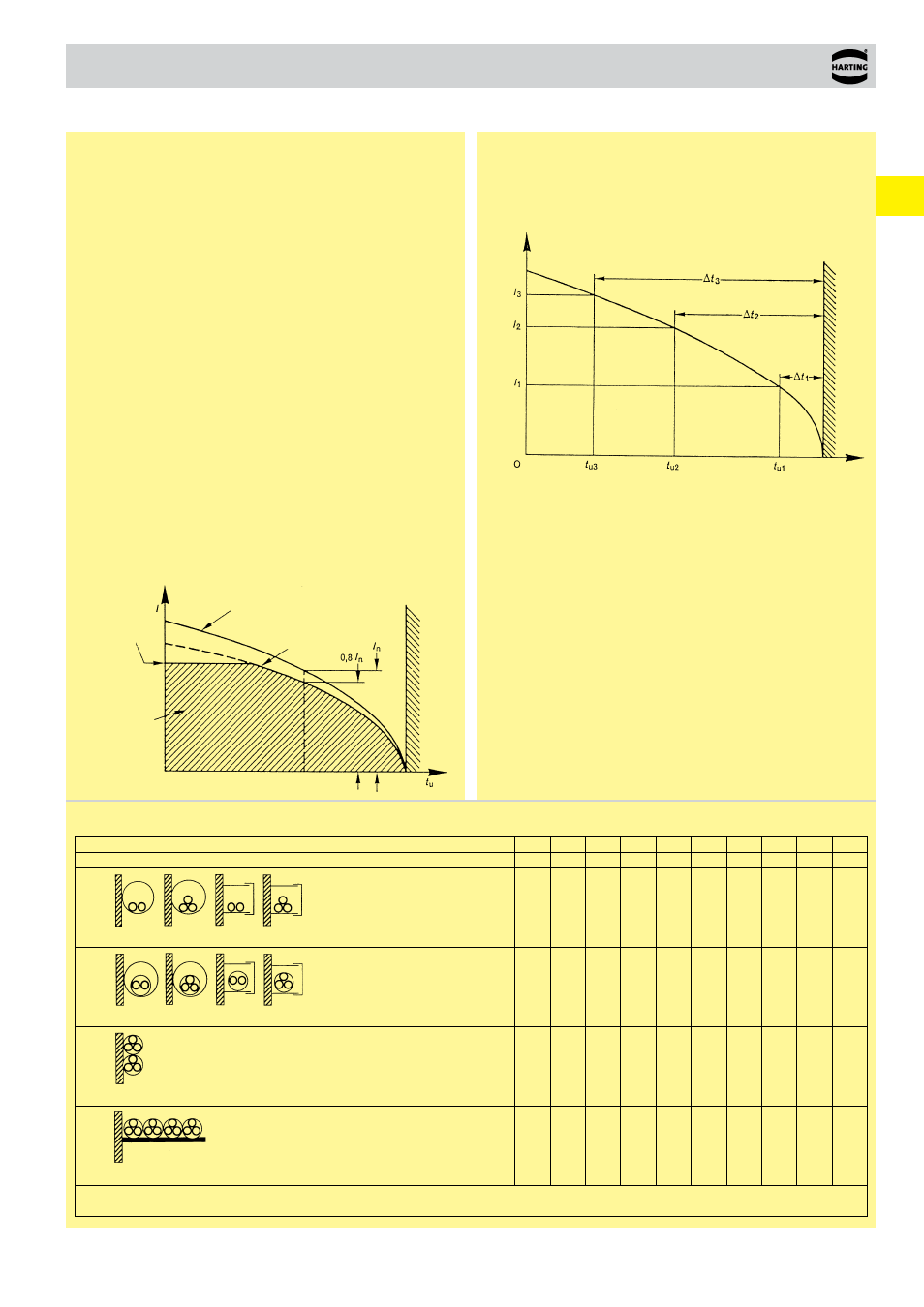
Example of a current capacity curve
Definition: The rated current is the continuous, not interrupted
current a connector can take when simultaneous power on all con-
tacts is given, without exceeding the maximum temperature.
Example of a current carrying curve
Acc. to DIN EN 61 984 the sum of ambient temperature and the
temperature rise of a connector shall not exceed the upper limiting
temperature. The limiting temperature is valid for a complete con-
nector, that means insert plus housing.
As a result the insert gives the limit for the temperature of a com-
plete connector and thus housings as well.
In practice it is not usual to load all terminals simultaneously with
the maximum current. In such a case one contact can be loaded
with a higher current as permitted by the current capacity curve, if
less than 20 % of the whole is loaded.
However, for these cases there are no universal rules. The
limits have to be determined individually from case to case. It is
recommended to proceed in accordance with the relevant rules of
the DIN EN 60 512-5-2.
Current carrying capacity of copper wires
Ambient temperature
Permissible upper temperature-limit
set by applied materials
Permissible upper limiting temperature
set by applied materials
basic curve
corrected curve
permissible
operation
range
Upper current
limit set by
external factors,
i.e. connectable
wire gauge, given
current limit
Current carr
ying capacity
Depiction in accordance with DIN EN 60 204-1 for PVC-insulated copper wires in an ambient temperature of + 40 °C under permanent operating conditions.
For different conditions and temperatures, installations, insulation materials or conductors the relevant corrections have to be carried out.
Diameter [mm²] of single wires in a three-phase system
0.75 1
.0
1.5 2.5
4
6
10
16
25
35
Type of installation
B1
Conductors/single core cables in conduit and cable trunking systems
8.6
10.3 13.5 18.3
24
31
44
59
77
96
B2
Cables in conduit and cable trunking systems
8.5
10.1 13.1 17.4
23
30
40
54
70
86
C
Cables on walls
9.8
11.7 15.2 21
.0
28 36 50 66 84 104
E
Cables on open cable trays
10.4 12.4 16.1 22
.0
30 37 52 70 88 110