00 . 19 terminations technology – Northern Connectors Harting HAN Industrial Rectangular Connectors User Manual
Page 25
Han
00
.
19
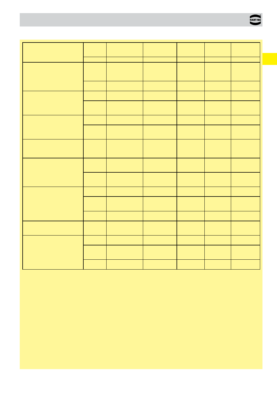
Terminations technology
Insert
Wire
gauge
Stripping length
Tightening
torque
Max. cable
insulation
diameter
Size
hexagon
recess
Insert dimension
for cable
indication (ISK)
(mm²)
(mm)
(Nm)
(mm)
(SW)
(mm)
Han
®
C module with axial screw
terminal
2.5 ... 8
2.5 mm²:
4 mm²:
6 mm²:
8 mm²:
5+1
5+1
8+1
8+1
2.5 mm²:
4 mm²:
6 mm²:
8 mm²:
1.5
1.5
2
2
4
4
6
8.2
2
5.2
6 ... 10
6 mm²:
10 mm²:
8+1
11+1
6 mm²:
10 mm²:
2
2
6
8.2
2
5.2
Han
®
K3/0 straight
25 ... 40
25 mm²:
40 mm²:
22
22
25 mm²:
40 mm²:
8
8
15
5
8.2
35 ... 70
35 mm²:
50 mm²:
70 mm²:
22
22
22
35 mm²:
50 mm²:
70 mm²:
8
9
10
15
5
8.2
Han
®
K3/0 angled
25 ... 40
25 mm²:
40 mm²:
22
22
25 mm²:
40 mm²:
8
8
15
5
9
35 ... 70
35 mm²:
50 mm²:
70 mm²:
22
22
22
35 mm²:
50 mm²:
70 mm²:
8
9
10
15
5
9
Han
®
K3/2 straight
35 ... 70
PE: 25 ... 40
35 mm²:
50 mm²:
70 mm²:
PE:
22
22
22
14
35 mm²:
50 mm²:
70 mm²:
8
9
10
power: 15
PE: 10
5
power: 8.2
PE: 7.2
Han
®
K3/2 angled
25 ... 40
25 mm²:
40 mm²:
PE:
22
22
14
25 mm²:
40 mm²:
8
8
power: 15
PE: 10
5
power: 9.0
PE: 7.2
35 ... 70
PE: 25 ... 40
35 mm²:
50 mm²:
70 mm²:
22
22
22
35 mm²:
50 mm²:
70 mm²:
8
9
10
power: 15
PE: 10
5
power: 9.0
PE: 7.2
Han
®
HC Modular 350
20 ... 35
20 mm²:
35 mm²:
19+1
19+1
20 mm²:
35 mm²:
8
8
19.5
5
13
35 ... 70
35 mm²:
50 mm²:
70 mm²:
19+1
19+1
19+1
35 mm²:
50 mm²:
70 mm²:
8
10
12
19.5
5
13
95 ... 120
95 mm²:
120 mm²:
19+1
19+1
95 mm²:
120 mm²:
14
16
19.5
5
13
Ground contact for
Han
®
HC Modular
35 ... 70
35 mm²:
50 mm²:
70 mm²:
19+1
19+1
19+1
35 mm²:
50 mm²:
70 mm²:
8
10
12
-
5
-
Han
®
HC Modular 650
60 ... 70
60 mm²:
70 mm²:
23+2
23+2
60 mm²:
70 mm²:
12
12
27
8
28
70 ... 120
70 mm²:
95 mm²:
120 mm²:
23+2
23+2
23+2
70 mm²:
95 mm²:
120 mm²:
12
14
16
26.5
8
28
150 ... 185
150 mm²:
185 mm²:
23+2
23+2
150 mm²:
185 mm²:
17
18
26.5
8
28
Overview inserts with axial screw terminal
Insulating base dimension for the cable marking (ISK)
Marking the proper cable position for the axial screw connection contact point:
The user can attach a marker to the cable sheathing in order to specify the proper point for tightening the axial screw on the connecting
cable. If the cable in pushed into the insulating base up to the marker (where the marker is flush with the upper edge of the insulating
base), then the cable is in the proper position and may be connected. The following figure (on the next page) illustrates this process
when using the Han
®
HC Modular 350 contact. The marker and the upper edge of the insulating base are at the same level (as indicated
by the dashed line).