Han-power® s with 1x han® q 4/2, metal, Han-power, S with 1x han – Northern Connectors Harting HAN Industrial Rectangular Connectors User Manual
Page 281: Q 4/2, metal, Q 4/2, metal features, Description, Technical characteristics
15
.
16
Power
Distribution
Han-Power
®
S with 1x Han
®
Q 4/2, metal
Features
• 6 IDCs/screw terminals + PE for 4 mm² up to 6
mm² wire gauge; 4 IDCs + PE for 10 mm² wire
gauge
• No interuption of the energy supply
• Space-saving and compact design
• Leading protective ground within the insert
• Assembly with standard tools
Description
Han-Power
®
S metal version allows the realisation of appli-
cations where a high degree of protection is required against
dust, splashed water and mechanical shock. This new variant
continues to support the user in providing simple installation
and maintenance practices but now offers greater protection
against harsh industrial environments.
Han-Power
®
S metal offers optimal handling characteristics
and now features an increased wire gauge range. It is now
possible to realise power distribution networks with wire gauge
up to 10 mm².
This power supply has to be realized with one Han-Compact
®
hood.
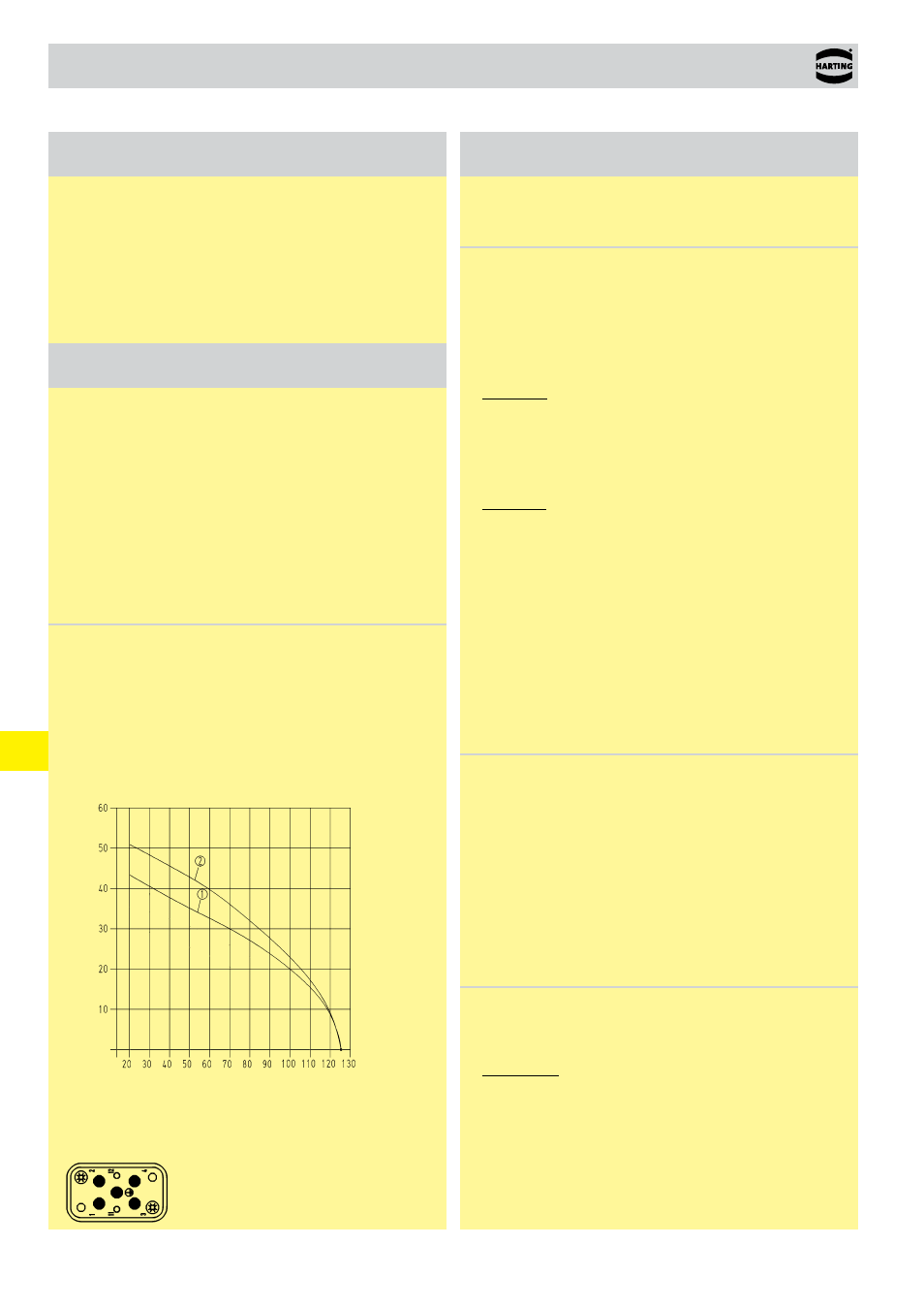
Current carrying capacity
The current carrying capacity of the connectors is limited by the
thermal load capability of the contact element material including
the connections and the insulating parts. The derating curve
is therefore valid for currents which flow constantly (non-inter-
mittent) through each contact element of the connector evenly,
without exceeding the allowed maximum temperature.
Measuring and testing techniques according to
DIN EN 60 512-5-2
Operating
current
Ambient temperature
➀ Han
®
Q 4/2 Wire gauge: 4 mm²
➁ Han
®
Q 4/2 Wire gauge: 6 mm²
Han
®
Q 4/2 fully loaded
with wire gauge 4x 6 mm²
Technical characteristics
Specifications
DIN EN 61 984
DIN EN 60 664-1
Han-Power
®
S
Number of contacts
- Power contacts
4 + PE
- Signal contacts
2
Electrical data
acc. to EN 61 984
Power side
40 A 400/690 V 6 kV 3
Rated current
40 A
Rated voltage conductor - ground 400 V
Rated voltage conductor - conductor 690 V
Rated impulse voltage
6 kV
Pollution degree
3
Signal side
10 A 250 V 4 kV 3
Rated current
10 A
Rated voltage
250 V
Rated impulse voltage
4 kV
Pollution degree
3
Rated voltage
acc. to UL/CSA
600 / 250 V
Insulation resistance
≥ 10
10
kΩ
Material
aluminium die-cast
Limiting temperatures
-40 °C ... +125 °C
Flammability acc. to UL 94
V 0
Mechanical working life
- mating cycles
≥ 500
Degree of protection acc. to DIN EN 60 529 IP 65
Contacts
Material
copper alloy
Surface
- hard-silver plated
3 µm Ag
- hard-gold plated
2 µm Au over 3 µm Ni
Contact resistance
≤ 0.3 mΩ
Crimp terminal
- mm²
4 ... 10 mm² /
0.14 ... 2.5 mm²
- AWG
12 ... 8 / 26 ... 14
Max. insulation diameter
- Power contacts
5 mm
Cables
Design of conductor acc. to
DIN VDE 0281
DIN EN 60 228
Single strand
Wire gauge
4 mm²
- Number of single strands
56 x 0.3 mm ∅
- Outer diameter
4.2 mm
Wire gauge
6 mm²
- Number of single strands
84 x 0.3 mm ∅
- Outer diameter
4.8 mm
Wire gauge
10 mm²
- Number of single strands
80 x 0.4 mm ∅
- Outer diameter
6.3 mm