00 . 17 terminations technology, Axial screw terminal, Remarks on the axial screw technique – Northern Connectors Harting HAN Industrial Rectangular Connectors User Manual
Page 23
Han
00
.
17
Terminations technology
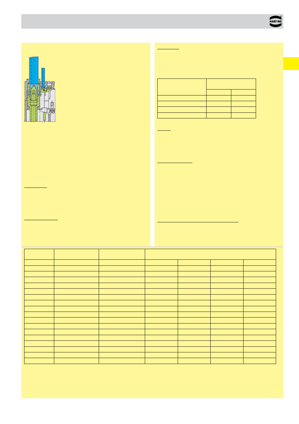
Axial screw terminal
This termination combines the benefits of screw and crimp termi-
nations:
● Less space required
● Easy handling
● No special tools
Remarks on the axial screw technique
The wire gauges mentioned in the catalogue refer to geometric
wire gauges of cables.
Background:
According to DIN VDE 0295 for cables and insulated wires the
wire gauge will be determined by conductance (Ω/km) and maxi-
mum wire diameter. A minimum cable diameter is not specified!
(Example:nominal wire gauge 95 mm² → real, geometric wire
gauge 89 mm²)
Recommendation:
The use of cables with an extreme geometric wire gauge deviati-
on should be checked separately with the use of the axial screw
termination.
Strain relief:
For safe operation the cable must be fixed at an adequate
distance from the terminal to ensure that the contact is protected
against radial stress.
Details for professional strain relief design can be found in the
standard DIN VDE 0100-520: 2003-06 (see enclosed table).
Outer cable diameter
(mm)
Maximum fixing distance
(mm)
horizontal
vertical
D
≤ 9
250
400
9 < D < 15
300
400
15 < D < 20
350
450
20 < D < 40
400
550
Cables:
The axial screw technology is developed for wires according to
DIN EN 60 228 class 5 (see table: Wire assembly according to
DIN EN 60 228). Deviating cable assemblies have to be tested
separately.
Assembly remarks:
Before starting the assembly the user must ensure that the axial
cone is screwed fully downward to completely open the contact
chamber.
After stripping the cable insulation the strands must not be
twisted and the maximum cable insulation must not exceed the
recommended dimension.
Insert the wire completely into the contact chamber until the
copper strands reach the bottom. Keep the cable in position
while applying the recommended tightening torque.
Maintenance of the axial screw termination:
After initial assembly it is only allowed to reapply the recommen-
ded tightening torque once in order to avoid damage to individual
cable strands.
Wire gauge
(mm²)
Stranded wires DIN
EN 60 228 class 2
Fine stranded wires
DIN EN 60 228 class 5
Super fine stranded wires DIN EN 60 228 class 6
0.5
7 x 0.30
16 x 0.20
28 x 0.15
64 x 0.10
131 x 0.07
256 x 0.05
0.75
7 x 0.37
24 x 0.20
42 x 0.15
96 x 0.10
195 x 0.07
384 x 0.05
1
7 x 0.43
32 x 0.20
56 x 0.15
128 x 0.10
260 x 0.07
512 x 0.05
1.5
7 x 0.52
30 x 0.25
84 x 0.15
192 x 0.10
392 x 0.07
768 x 0.05
2.5
7 x 0.67
50 x 0.25
140 x 0.15
320 x 0.10
651 x 0.07
1280 x 0.05
4
7 x 0.85
56 x 0.30
224 x 0.15
512 x 0.10
1040 x 0.07
6
7 x 1.05
84 x 0.30
192 x 0.20
768 x 0.10
1560 x 0.07
10
7 x 1.35
80 x 0.40
320 x 0.20
1280 x 0.10
2600 x 0.07
16
7 x 1.70
128 x 0.40
512 x 0.20
2048 x 0.10
25
7 x 2.13
200 x 0.40
800 x 0.20
3200 x 0.10
35
7 x 2.52
280 x 0.40
1120 x 0.20
50
19 x 1.83
400 x 0.40
705 x 0.30
70
19 x 2.17
356 x 0.50
990 x 0.30
95
19 x 2.52
485 x 0.50
1340 x 0.30
120
37 x 2.03
614 x 0.50
1690 x 0.30
150
37 x 2.27
765 x 0.50
2123 x 0.30
185
37 x 2.52
944 x 0.50
1470 x 0.40
240
61 x 2.24
1225 x 0.50
1905 x 0.40
Wire assembly according to DIN EN 60 228