Calibrate pressure sensor, Down force status, Bar graphs on run screen – Kinze Ag Leader Integra User Manual
Page 200: Calibrate pressure sensor down force status, Alibrate, Ressure, Ensor, Orce, Tatus, Raphs on
184
Firmware Version 5.2
PWM Frequency
The frequency that the PWM control valve is pulsed at should be set to 200.
Calibrate Pressure Sensor (Grayed out for Monitor Only)
Pressure Sensor Enable (Grayed out for Monitor Only)
Row Unit Sensors - Sensors 1-4 check boxes. Enable or disable gauge wheel sensors.
C
ALIBRATE
P
RESSURE
S
ENSOR
(Only able to calibrate when Control Mode has been selected)
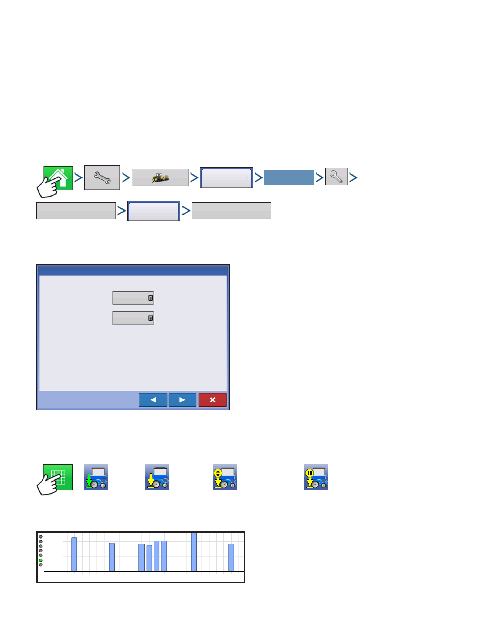
Press: Home button > Setup (wrench) button > Configuration (tractor) button > Configuration tab > your
specific configuration > Setup (wrench) button > Down Force button > Channel 1 (or Channel 2) >
Calibrate Pressure Sensor button
Setpoint - enter the current pressure of the system
found on the mechanical pressure gauge on the
valve block
Slope - pressure sensor calibration, do not adjust
this value
D
OWN
F
ORCE
S
TATUS
Press: Map button. Icons on the lower right side of Map Screen show the status of Down Force.
Active
Inactive
Manual Mode
Manual Hold
B
AR
G
RAPHS ON
R
UN
S
CREEN
Bar Graphs on Run Screen shows force on
Gauge Wheel and Down force being applied to
row unit. Press bar graph to advance to next
graph. Bar graph may also contain graphs for
Advanced Seed Monitoring.
Configuration
Select Your Specific
Configuration
Down
Force
Channel 1
Calibrate
Pressure Sensor
Pressure Sensor Calibration: Step 2 of 3
Set Point
0 PSI
Slope
0.75 PSI/mV
Enter the Setpoint and Slope for the Hydraulic Pressure Sensor
2
4
6
8
10
12
14
16
18
20
22
24
200 lb
150 lb
100 lb
50 lb
Gauge Wheel 203 lb